1. Introduction and Overview
The EBYTE M31-XXAX0080G is a distributed IO host module designed for industrial acquisition and control applications. It supports both Modbus TCP and Modbus RTU protocols, allowing for flexible integration into various systems. This device facilitates simultaneous access by up to 5 clients and supports standard Modbus function codes (01, 02, 03, 04, 05, 06, 15, 16).
The M31 series features a scalable design, enabling users to expand functionality by connecting up to 16 additional IO expansion modules as needed. This modular approach helps optimize costs and adapt to specific on-site environmental requirements. The module also includes a status diagnosis function to monitor the real-time communication status of connected IO modules.
2. Key Features
- Protocol Support: Supports standard Modbus RTU and Modbus TCP protocols, including protocol conversion. Compatible with various configuration software, PLCs, and touch screens.
- Connectivity: Features RS485 for acquisition control I/O and an Ethernet port for network-based I/O control. Supports simultaneous access by up to 5 host clients.
- Configuration: Allows custom Modbus address settings and supports 8 baud rate configurations. DHCP and static IP addressing are supported for network setup.
- Expandability: Utilizes a distributed IO mode, allowing connection of up to 16 IO expansion modules to enhance functionality.
- Installation: Designed for versatile installation, supporting both positioning holes and guide rail mounting.
- Diagnostic Function: Includes a self-contained status diagnosis function to monitor the communication status of IO modules in real-time.
3. Product Dimensions
Understanding the physical dimensions of the M31-XXAX0080G module is crucial for proper installation and integration into control cabinets or systems.
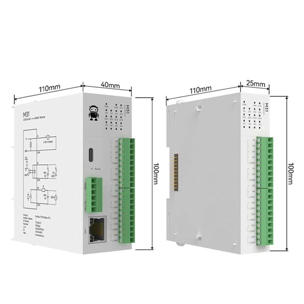
Figure 3.1: The EBYTE M31-XXAX0080G module measures approximately 110mm in length, 40mm in width (excluding connectors), and 100mm in height. The side view shows a width of 25mm for the main body and 110mm in length, 100mm in height.
4. Setup
4.1 Physical Connections
Connect the power supply (DC 6-36V), RS485 communication lines, and Ethernet cable to the respective ports on the module. Ensure all connections are secure and correctly polarized.

Figure 4.1: Diagram illustrating the Ethernet (RJ45) and RS485 connections on the M31 module. The module supports dual control via both interfaces.
4.2 Modbus Address Configuration (Dial Code)
The Modbus address for the module can be quickly configured using the built-in dial code switches, eliminating the need for a host computer for this initial setup.

Figure 4.2: Image showing the dial code switches used for configuring Modbus addresses. Refer to the product's detailed specification sheet for specific switch settings and corresponding Modbus addresses.
5. Operating Instructions
5.1 Basic Functions
The M31-XXAX0080G module supports various switching and analog inputs/outputs, enabling it to interface with a wide range of industrial sensors and actuators.

Figure 5.1: This diagram illustrates the basic functions: Digital Inputs (DI) for devices like proximity switches and limit switches; Analog Inputs (AI) for temperature and liquid level acquisition; Digital Outputs (DO) for controlling devices such as water pumps and lighting; and Analog Outputs (AO) for motors and control valves.
5.2 Rapid Debugging and Parameter Configuration
Utilize the provided upper computer software for rapid debugging and parameter configuration of the equipment. This software allows for real-time monitoring and adjustment of module settings.

Figure 5.2: Screenshot of the upper computer software interface, showing indications for DI status, DO state switching, AI input acquisition, and AO output range. This software facilitates quick setup and diagnostics.
5.3 Modbus System Integration
The M31 module is designed for seamless integration with existing Modbus systems, supporting various industrial control components.

Figure 5.3: The module supports connection to HMI touch screens, configuration software, and PLCs without requiring complex protocol matching, simplifying system setup.
5.4 Analog Input (AI) Models
The module offers optional current/voltage acquisition types for analog inputs, with a configurable input range to adapt to different sensors and transmitters.

Figure 5.4: Illustration of AI input types, including adaptability to 0-20mA sensors and compatibility with 4-20mA transmitters. The input range is configurable.
6. Maintenance
To ensure optimal performance and longevity of your EBYTE M31-XXAX0080G module, follow these general maintenance guidelines:
- Regular Inspection: Periodically check all cable connections for looseness or damage.
- Environmental Control: Ensure the module operates within its specified temperature and humidity ranges to prevent damage.
- Cleaning: Keep the module free from dust and debris. Use a soft, dry cloth for cleaning. Avoid liquid cleaners.
- Firmware Updates: Check the manufacturer's website for any available firmware updates to improve performance or address issues.
7. Troubleshooting
If you encounter issues with your M31-XXAX0080G module, consider the following basic troubleshooting steps:
- No Power: Verify the power supply connection and ensure it provides the correct voltage (DC 6-36V). Check power indicator LEDs.
- Communication Failure:
- Check RS485 wiring for correct polarity (A/B) and termination resistors if applicable.
- Verify Ethernet cable connection and network settings (IP address, subnet mask, gateway).
- Confirm Modbus address and baud rate settings match the host controller.
- Check the module's status diagnosis function for communication errors.
- Incorrect I/O Readings/Control:
- Ensure sensors and actuators are correctly wired to the module's I/O terminals.
- Verify the configuration of input/output types and ranges in the software.
- Check for any physical damage to I/O terminals or connected devices.
- Module Not Responding: Try power cycling the module. If the issue persists, consult the detailed product manual or contact technical support.
8. Specifications
The following table provides a comparison of specifications and parameters for various M31 series models, including the M31-XXAX0080G host module and compatible expansion modules.

Figure 8.1: Detailed table comparing various M31 series models, their attributes, and the number of Digital Input (DI), Analog Input (AI), Digital Output (DO), and Analog Output (AO) channels. The M31-XXAX0080G is listed as a host module with 8 Digital Outputs.
General Specifications for M31-XXAX0080G:
- Model Number: M31-XXAX0080G
- Manufacturer: EBYTE
- Digital Output (DO): 8 channels
- Communication Interfaces: RS485, Ethernet (RJ45)
- Protocols: Modbus TCP, Modbus RTU
- Client Access: Supports up to 5 simultaneous clients
- Expansion: Supports up to 16 IO expansion modules
- Power Supply: DC 6-36V (typical)
- Baud Rate Configurations: 8 options
- IP Configuration: DHCP and Static IP support
9. Warranty and Support
EBYTE products typically come with a standard manufacturer's warranty. For specific warranty terms, duration, and conditions, please refer to the warranty card included with your product or visit the official EBYTE website. Keep your purchase receipt as proof of purchase.
For technical support, troubleshooting assistance beyond this manual, or inquiries regarding repairs and spare parts, please contact EBYTE customer service through their official channels. Contact information can usually be found on the product packaging or the manufacturer's website.