Yarzkrg N1201SA PS200
N1201SA PS200 Multi-Function Antenna Analyzer User Manual
Comprehensive guide for operation, maintenance, and troubleshooting.
1. Product Overview
The Yarzkrg N1201SA PS200 is a versatile multi-function antenna analyzer designed for measuring various parameters of antennas and RF circuits. It provides capabilities for measuring Resistance, Reactance, SWR (Standing Wave Ratio), and S11 (Return Loss) across a wide frequency range. This instrument is equivalent to a single-port vector network analyzer, making it an essential tool for radio enthusiasts, engineers, and technicians.
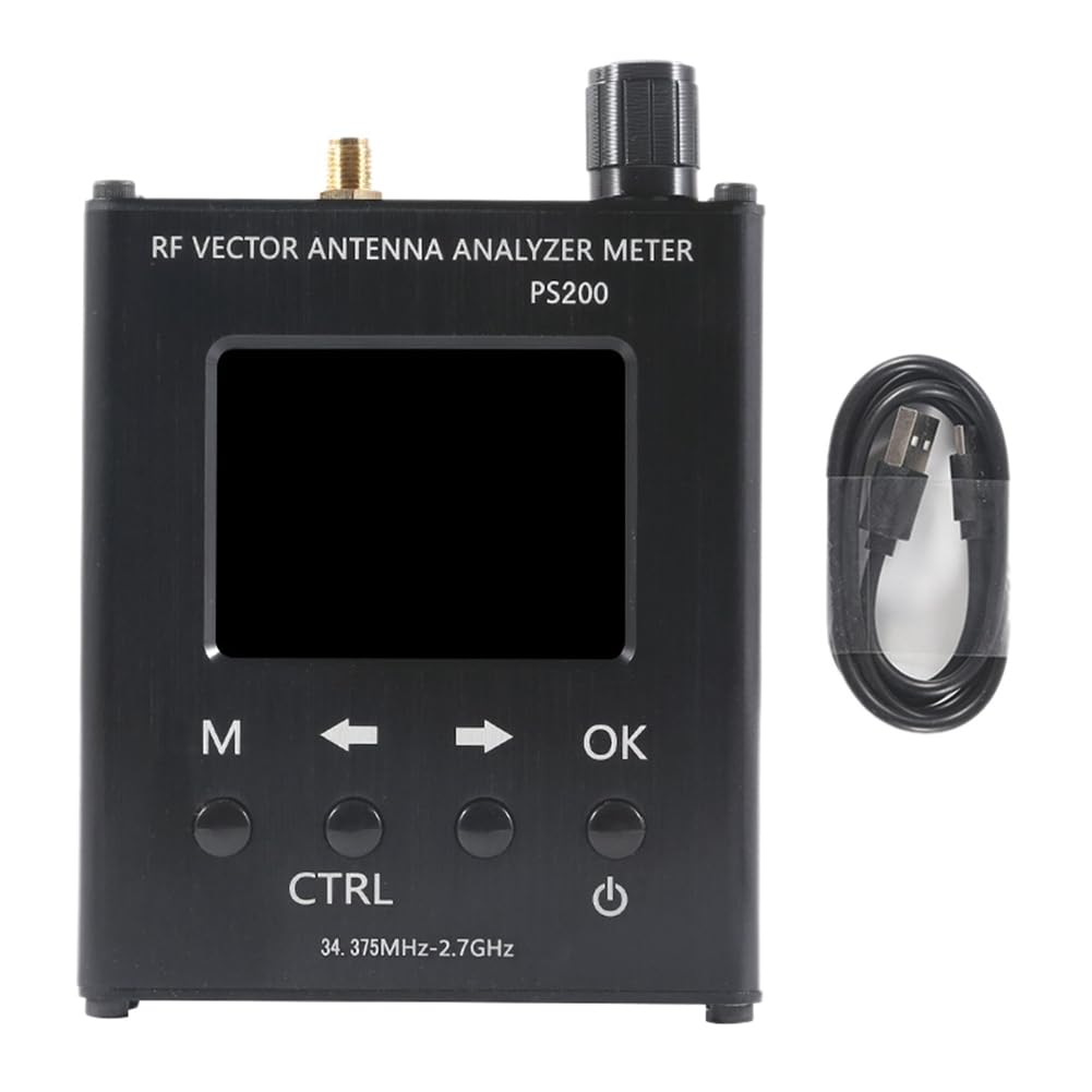
Figure 1.1: Front view of the N1201SA PS200 Antenna Analyzer, showcasing its display, control buttons, and the included USB data cable.
2. Package Contents
Upon opening the package, please verify that all components are present and in good condition:
- 1 x N1201SA PS200 Antenna Analyzer Unit
- 1 x USB Data Cable
If any items are missing or damaged, please contact customer support immediately.
3. Technical Specifications
The following table details the technical specifications of the N1201SA PS200 Antenna Analyzer:
| Parameter | Value |
|---|---|
| Frequency Range | 34.375 MHz - 2.7 GHz |
| Frequency Spacing | 1 kHz |
| Display | 2.4-inch TFT, 320x240 pixels (QVGA) |
| Battery Capacity | 2000 mAh (7.4 Wh) |
| Charging Current | 400 mA (Micro USB port, for charging only) |
| Automatic Shutdown | Adjustable (Normally On; 5 minutes - 60 minutes) |
| Measurement Modes | Resistance, Reactance, SWR, S11 |
| Resolution Ratio | 4 significant figures |
| Frequency Accuracy | 55 ppm |
| RF Connector | SMA-K |
| Impedance Measurement Range | 0.1 Ω ~ 1000 Ω (absolute impedance value) |
| SWR Measurement Range | 1.000 ~ 65 |
| S11 (dB) Measurement Range | 0 dB ~ -60 dB |
| Directivity | < 35 dB (35 MHz - 2 GHz after calibration) |
| Output Level | -18 dBm |
| Working Temperature | 0 ℃ ~ 40 ℃ |
| Atmospheric Pressure | 860 hPa ~ 1060 hPa |
| Product Dimensions (L x W x H) | 4.72 x 1.97 x 0.79 inches |
| Item Weight | 315 Grams |
| Color | Black |
| Power Source | AC/DC |
4. Setup and Initial Use
4.1 Charging the Device
Before first use, fully charge the N1201SA PS200 using the provided USB data cable. Connect the micro USB end of the cable to the "CHARGING" port on the side of the analyzer and the other end to a standard USB power adapter (not included) or a computer USB port. The charging current is 400mA.

Figure 4.1: Side view of the analyzer, highlighting the Micro USB charging port and the reset button.
4.2 Powering On/Off
To power on the device, press and hold the power button (usually marked with a circle and vertical line symbol) located on the front panel. To power off, press and hold the same button until the display turns off. The device also features an adjustable automatic shutdown function, which can be set from 5 to 60 minutes, or disabled for continuous operation.
4.3 Connecting to an Antenna/Load
Connect the antenna or RF load you wish to analyze to the SMA-K connector on the top of the device. Ensure the connection is secure. It is recommended to use high-quality RF cables and connectors for accurate measurements. Avoid using excessively long leads as this can affect measurement accuracy.

Figure 4.2: Top-angled view of the analyzer, illustrating the SMA-K connector for antenna or load connection.
5. Operating the Analyzer
5.1 User Interface and Controls
The N1201SA PS200 features a 2.4-inch TFT display and several control buttons for navigation and operation:
- M (Menu) Button: Accesses the main menu or switches between display modes.
- Arrow Buttons (Left/Right): Navigate through menu options or adjust values.
- OK Button: Confirms selections or enters sub-menus.
- CTRL (Control) Button: Provides additional control functions, context-dependent.
- Rotary Encoder: Used for fine-tuning frequency or other parameters.
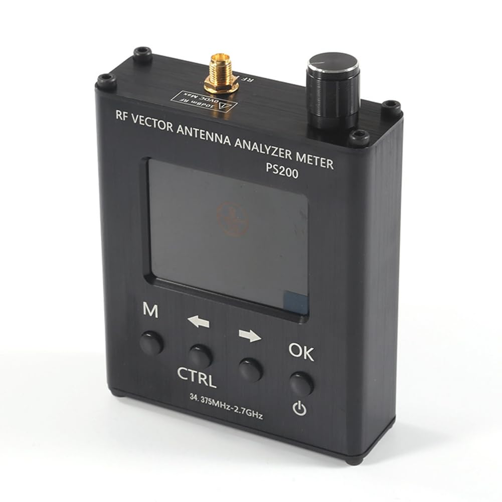
Figure 5.1: Top-down view of the analyzer, highlighting the rotary encoder and the layout of the control buttons.
5.2 Calibration Procedure
For accurate measurements, calibration is crucial. Follow these steps:
- Warm-up: Power on the instrument and allow it to warm up for at least 15 minutes before performing any measurements or calibration. This ensures measurement and calibration accuracy.
- Prepare Calibration Standards: Use appropriate calibration standards (Open, Short, Load) for the frequency range you intend to measure.
- Perform Calibration: Follow the on-screen instructions to perform the calibration. The calibration cable, if marked, may be used directly without recalibration for subsequent uses.
- Verify Calibration: After calibration, you can verify the accuracy by measuring known loads.
5.3 Taking Measurements
Once calibrated, you can proceed with measurements:
- Select the desired measurement mode (Resistance, Reactance, SWR, or S11) using the menu.
- Adjust the frequency using the rotary encoder or arrow buttons to the desired test frequency.
- The display will show the measured values in real-time.

Figure 5.2: The analyzer's display showing typical measurement results for frequency, resistance (R), reactance (X), VSWR, and S11 (dB).
The display provides detailed information, including the current frequency, resistance (R), reactance (X), VSWR, and S11 (Return Loss) in dB. The resolution ratio is 4 significant figures, and frequency accuracy is 55 ppm.
6. Maintenance and Care
Proper maintenance ensures the longevity and accuracy of your N1201SA PS200 Antenna Analyzer:
- Cleaning: Use a soft, dry cloth to clean the device. Do not use abrasive cleaners or solvents.
- Battery Care: To preserve battery life, avoid fully discharging the battery frequently. If storing for extended periods, charge the battery to about 50% and store in a cool, dry place.
- Storage: Store the analyzer in a clean, dry environment, away from extreme temperatures, humidity, and direct sunlight.
- Connector Care: Keep the SMA-K connector clean and free from dust or debris. Avoid overtightening connections.
7. Troubleshooting
This section addresses common issues you might encounter:
7.1 Inaccurate Measurements
- Calibration: Ensure the device has been properly calibrated for the frequency range of interest. Recalibrate if necessary, especially after significant temperature changes or if the device has been moved.
- Warm-up Time: Always allow the instrument to warm up for at least 15 minutes before measurement or calibration.
- Cables and Connectors: Verify that all RF cables and connectors are in good condition and properly connected. The craftsmanship of the leads affects accuracy; avoid using overly long or poor-quality cables.
- Interference: Strong wireless signals in the vicinity can cause interference and inaccurate measurements. Perform measurements in an environment free from strong RF interference.
- Understanding Concepts: If you are new to impedance measurement or vector network analysis, consult relevant instructions and tutorials to better understand the principles.
7.2 Device Not Powering On
- Battery Charge: Ensure the battery is sufficiently charged. Connect the device to a power source and allow it to charge for some time.
- Reset: Locate the reset button (often a small pinhole) on the side of the device (refer to Figure 4.1) and gently press it with a thin, non-metallic object.
7.3 Display Issues
- Brightness: Check if the display brightness is set too low.
- Power Cycle: Try turning the device off and on again.
8. Warranty and Support
Specific warranty information for the Yarzkrg N1201SA PS200 Antenna Analyzer is not provided in this manual. Please refer to the product packaging or the retailer's website for warranty details.
For technical support, troubleshooting assistance beyond this manual, or inquiries regarding repairs, please contact the manufacturer or your point of purchase. Keep your purchase receipt or proof of purchase handy when contacting support.
Related Documents - N1201SA PS200
 |
AAI N1201SA Series Vector Impedance Analyzer Product Manual This product manual provides detailed information on the AAI N1201SA series handheld radio frequency vector impedance analyzer, covering its features, technical specifications, operation, and calibration procedures. |
 |
AAI N2201SS Series Vector Impedance Analyzer Product Manual This product manual provides detailed information on the AAI N2201SS Series Vector Impedance Analyzer, including its features, technical specifications, operational functions, calibration procedures, safety guidelines, and contact information for after-sales support. |
 |
MULTI MLD-18HW Clamp-Type Small Leakage Detector Instruction Manual Instruction manual for the MULTI MLD-18HW clamp-type small leakage detector. Covers safety, specifications, parts, handling, after-sales service, and warranty information. |
 |
SARK-110 Vector Impedance Antenna Analyzer User Manual - Comprehensive Guide This user manual provides detailed instructions and specifications for the SARK-110 Vector Impedance Antenna Analyzer, covering its features, operation, modes, and technical details. |
 |
Velocity Commerce PS200 Portable Speaker User Manual and Features Official user manual for the Velocity Commerce PS200 portable Bluetooth speaker. Learn about its functions, operations, connectivity, and FCC compliance. |
 |
Keysight FieldFox Handheld Analyzers: 4/6.5/9/14/18/26.5 GHz Explore the Keysight FieldFox series of handheld RF and microwave analyzers, offering advanced capabilities for spectrum analysis, vector network analysis (VNA), cable and antenna testing, and 5G measurements across various frequency bands. Discover their rugged design, ease of use, and comprehensive features for field testing. |
Ask a question about this manual
Ask about setup, troubleshooting, compatibility, parts, safety, or missing instructions. Manuals+ will review the question and use this page’s manual context to help answer it.