PEMENOL GY21279-2-FBA
PEMENOL 4-Digit Digital RGB LED Clock DIY Kit User Manual
Model: GY21279-2-FBA
1. Product Overview
The PEMENOL 4-Digit Digital RGB LED Clock DIY Kit is a utility soldering kit designed for assembling a functional electronic clock. This kit is an excellent educational tool for beginners and DIY enthusiasts interested in electronics and soldering.
Once assembled, the clock can display the current time, date, and temperature in real-time. It features a multi-color RGB LED display, allowing for customizable color settings or random color display. The brightness is adjustable, offering both automatic and manual control. The clock also includes an alarm function with power failure memory and four adjustable music tracks.

Figure 1.1: The PEMENOL 4-Digit Digital RGB LED Clock (assembled) and its complete DIY kit components, including the PCB, display, resistors, capacitors, and power cable.
Key Features:
- 4-Digit LED Display: Clear 1.36-inch digital tube display.
- Real-time Display: Shows time, date, and temperature.
- RGB LED Colors: Multi-color display with customizable or random color options.
- Adjustable Brightness: Automatic and manual brightness settings.
- Alarm Function: Three sets of alarm settings (daily, Mon-Fri, Mon-Sat) with four adjustable music tracks.
- Power Failure Memory: Retains settings after power loss.
- Time and Temperature Formats: Supports 12H/24H time and ℃/℉ temperature formats.
- User-Friendly Controls: Two adjustment buttons for easy operation.

Figure 1.2: Visual representation of the clock's features including time, date, temperature display, RGB digits, brightness levels, alarm settings, and memory function, along with its dimensions.
2. Safety Information
Please read and understand all safety instructions before beginning assembly and operation of the PEMENOL 4-Digit Digital RGB LED Clock DIY Kit. Failure to follow these instructions may result in injury or damage to the product.
- Soldering Safety:
- Always work in a well-ventilated area to avoid inhaling solder fumes.
- Use appropriate personal protective equipment, including safety glasses, to protect your eyes from splashes or fumes.
- Ensure your soldering iron is on a heat-resistant stand when not in use.
- Avoid touching the hot tip of the soldering iron or freshly soldered components.
- Keep a fire extinguisher or fire blanket nearby.
- Electrical Safety:
- Do not connect the clock to power until all components are correctly soldered and inspected.
- Ensure the power supply used matches the specified voltage (5V).
- Avoid contact with live electrical circuits.
- Component Handling:
- Handle electronic components with care. Some components are sensitive to static electricity.
- Keep small components out of reach of children to prevent choking hazards.
3. Assembly Instructions (Setup)
This kit requires basic knowledge of electronic theory and soldering skills. The LED board is pre-soldered, but you will need to solder several electronic components onto the board. Follow the clear connection diagrams and labels provided on the PCB.
Required Tools (Not Included):
- Soldering Iron
- Solder Wire
- Solder Wick or Desoldering Pump (optional, for corrections)
- Wire Cutters/Nippers
- Pliers (optional)
- Multimeter (optional, for testing)
Assembly Steps:
- Identify Components: Unpack all components and identify them using the provided component list and the PCB labels. Refer to Figure 3.1 for component identification on the board.
- Solder Resistors: Solder the resistors (e.g., 10KΩ) into their designated positions on the PCB. Resistors are not polarized, so orientation does not matter.
- Solder Capacitors: Solder the capacitors. Pay attention to polarity for electrolytic capacitors if present (though most in this kit are likely non-polarized ceramic capacitors).
- Solder Diodes/LEDs: Solder any diodes or individual LEDs, ensuring correct polarity (long leg usually positive). The main display LEDs are pre-soldered.
- Solder IC Sockets (if applicable): If the kit includes IC sockets, solder them first, then insert the ICs after all soldering is complete to protect them from heat.
- Solder Transistors/ICs: Solder transistors and integrated circuits (ICs) carefully, ensuring correct orientation as indicated by notches or dots on the component and corresponding marks on the PCB.
- Solder Buttons and Connectors: Solder the push buttons, power connector (Micro USB), and any other connectors.
- Solder Buzzer and Crystal: Solder the buzzer and the 32.768KHz crystal.
- Solder Battery Holder: Solder the button cell battery holder for the real-time clock (RTC) module.
- Review Soldering: Carefully inspect all solder joints for cold joints, bridges, or missing connections. Ensure all component leads are trimmed short after soldering.
- Assemble Casing: Once soldering is complete and verified, carefully place the assembled PCB into the acrylic casing. Secure it with the provided screws.

Figure 3.1: Detailed view of the printed circuit board (PCB) with labels indicating the placement of various components such as SW1 (Buzzer), Thermistor, Button Cell holder, Photoresistor, SW2 (Buttons), 32.768KHz Crystal, DS1302 Chip, IC, and 5V Power Supply.

Figure 3.2: Electronic schematic diagram illustrating the circuit connections and components of the PEMENOL RGB LED Clock, including the microcontroller, display, power input, and various sensors/buttons.

Figure 3.3: Individuals engaged in the assembly process of the clock kit, demonstrating the hands-on nature of the project, and the final product in use.
4. Operating Instructions
After successful assembly, connect the clock to a 5V USB power source using the provided cable. The clock will power on and display the current time or default settings.
Basic Operation:
- Power On/Off: The clock powers on automatically when connected to a USB power source. There is no dedicated power button.
- Setting Time/Date: Use the '+' and '-' buttons (SW1 and SW2 on the PCB, or labeled buttons on the casing) to navigate through settings and adjust values. Refer to the specific button functions for setting time, date, and alarm.
- Switching Display Modes: The clock cycles through time, date, and temperature displays automatically.
Advanced Settings:
- 12H/24H Time Format: Press and hold a specific button (refer to the kit's detailed instructions if provided, otherwise experiment with '+' or '-' buttons) to toggle between 12-hour and 24-hour time formats.
- ℃/℉ Temperature Format: Similarly, press and hold another button to switch between Celsius and Fahrenheit temperature units.
- RGB LED Color Adjustment: The clock features multi-color RGB LEDs. You can cycle through preset colors or set a random color display mode. Use the adjustment buttons to select your preferred color mode.
- Brightness Control: The clock supports both automatic and manual brightness adjustment. Use the buttons to switch between modes or adjust manual brightness levels.
- Alarm Settings:
- Set up to three independent alarms.
- Choose alarm frequency: daily, Monday-Friday, or Monday-Saturday.
- Select from four adjustable music tracks for the alarm sound.
- The alarm can be turned on or off as needed.
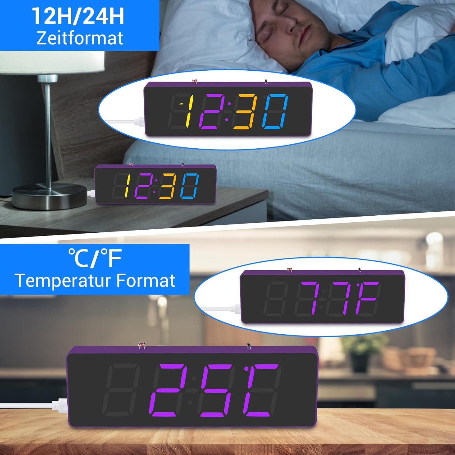
Figure 4.1: The clock displaying time in both 12-hour (with AM/PM indicator) and 24-hour formats, and temperature in both Celsius and Fahrenheit units.

Figure 4.2: Examples of the clock displaying time in different RGB colors and demonstrating various brightness levels, from dim to bright.
5. Maintenance
Proper maintenance ensures the longevity and optimal performance of your PEMENOL RGB LED Clock.
- Cleaning:
- Wipe the acrylic casing with a soft, dry, lint-free cloth.
- Avoid using abrasive cleaners, solvents, or strong chemicals, as they may damage the acrylic or electronic components.
- Power Supply:
- Always use a stable 5V USB power source.
- Do not expose the clock to excessive voltage or current.
- Environment:
- Keep the clock in a dry environment, away from direct sunlight, high temperatures, and humidity.
- Avoid placing the clock near strong magnetic fields.
- Battery Replacement (for RTC):
- The clock uses a Lithium-polymer button cell battery for its real-time clock (RTC) function, which maintains time during power outages.
- If the clock consistently loses time when unplugged, the battery may need replacement. Refer to the PCB diagram for the battery holder location.
- Ensure correct polarity when replacing the battery.
6. Troubleshooting
If you encounter issues with your PEMENOL RGB LED Clock, refer to the following troubleshooting guide:
| Problem | Possible Cause | Solution |
|---|---|---|
| Clock does not power on. |
|
|
| Display is dim or uneven. |
|
|
| Clock loses time when unplugged. |
|
|
| Buttons do not respond. |
|
|
7. Specifications
| Attribute | Value |
|---|---|
| Brand | PEMENOL |
| Model Number | GY21279-2-FBA |
| Product Dimensions (L x W x H) | 16.5 x 2.1 x 5 cm |
| Item Weight | 112 Grams |
| Color | RGB Purple Clock Kit |
| Style | Modern |
| Material | Acrylic |
| Shape | Cylinder |
| Power Type | Electric Cable (USB 5V) |
| Number of Pieces | 1 (assembled unit) |
| Bulb Type | LED |
| Display Type | Digital |
| Switch Style | Push Button |
| Special Functions | Calendar Display, Alarm Clock, Temperature Display, RGB Color Control, Brightness Adjustment, Power Failure Memory |
| Included Components | DIY Kit components, User Manual |
| Battery Included | Yes (1 Lithium-polymer for RTC) |
8. Warranty and Support
PEMENOL is committed to providing high-quality products and customer satisfaction. All PEMENOL products come with professional product manuals and are supported by a team of engineers.
For technical assistance, troubleshooting beyond this manual, or inquiries regarding your product, please contact PEMENOL customer support through the retailer's platform or the official PEMENOL website.
Please retain your purchase receipt as proof of purchase for any warranty claims.
Ask a question about this manual
Ask about setup, troubleshooting, compatibility, parts, safety, or missing instructions. Manuals+ will review the question and use this page’s manual context to help answer it.