1. Introduction
Thank you for choosing the PULME HSPY-400-1 DC Lab Switching Power Supply. This device is a high-precision, adjustable, and programmable power supply designed for laboratory, educational, and industrial applications. It features a micro-system with encoded-controlled fine and coarse adjustment knobs, a 4-digit LED display, and memory functions for efficient operation. This manual provides essential information for the safe and effective use of your power supply.
2. Safety Instructions
Please read and understand all safety instructions before operating the device. Failure to follow these instructions may result in electric shock, fire, or damage to the product.
- Power Source: Ensure the power supply is connected to a grounded outlet with the correct voltage (110V for this model).
- Environment: Operate the device in a dry, well-ventilated area. Avoid exposure to moisture, direct sunlight, or extreme temperatures.
- Ventilation: Do not block the ventilation openings on the device. The intelligent temperature control fan requires clear airflow for proper cooling.
- Overload Protection: The unit includes voltage overload, power overload, and short circuit protection. However, always operate within the specified voltage and current limits.
- Maintenance: Refer to the maintenance section for cleaning and care. Do not attempt to service the unit yourself. Contact qualified personnel for repairs.
- Grounding: The device is equipped with a grounding wire for safety. Ensure proper grounding at all times.
3. Product Overview
The PULME HSPY-400-1 is a compact and portable DC power supply featuring high accuracy and a user-friendly interface. It provides stable current output and clear readouts for precise control.
Key Features:
- High Accuracy: MPU micro-system with encoded-controlled fine and coarse adjustment.
- 4-Digit LED Display: Provides precise readings for voltage (0.01V) and current (0.001A).
- Storage and Recall Memory: Three programmable memory slots for frequently used settings.
- Constant Current (C.C.) and Constant Voltage (C.V.) Modes.
- Comprehensive Safety: Grounding wire, leakage protection, thermal protection, voltage overload, power overload, and short circuit protection.
- Intelligent Temperature Control Fan: Ensures effective heat dissipation and extends product life.
Front Panel Components:

Figure 3.1: Front panel layout with labeled controls. This image shows the display, adjustment knob, setting keys, output jacks, and power switch.
- Display: Shows voltage, current, and operating mode.
- Left/Right Buttons: Used for navigating settings.
- U/I (Voltage/Current Setting) Key: Toggles between voltage and current adjustment modes.
- Stop/Run Button: Controls output enable/disable.
- Adjustment Knob: Fine and coarse adjustment for voltage and current values.
- Output Jacks: Positive (red) and Negative (black) terminals for connecting loads.
- Power Switch: Turns the unit on or off.
Rear Panel Components:

Figure 3.2: Rear panel showing the AC power inlet, smart cooling fan, and VGA connection port for computer equipment.
- AC Power Inlet: For connecting the main power cord.
- Smart Cooling Fan: Activates when the internal temperature exceeds 50°C (122°F) to maintain optimal operating temperature.
- VGA Connection Line: Allows connection to computer equipment for advanced control or monitoring (if applicable to specific models).
4. Setup
Follow these steps to set up your PULME HSPY-400-1 DC Lab Switching Power Supply:
- Unpacking: Carefully remove the power supply and all accessories from the packaging. Verify that all components are present, including the power cord and output cables.
- Placement: Place the power supply on a stable, level surface, ensuring adequate space around the unit for ventilation. Do not place it near heat sources or in direct sunlight.
- Power Connection: Ensure the power switch on the front panel is in the OFF position. Connect the provided AC power cord to the AC power inlet on the rear panel of the power supply, then plug the other end into a grounded 110V AC power outlet.
- Load Connection: Connect your load to the output jacks on the front panel. Connect the positive (+) terminal of your load to the red output jack and the negative (-) terminal of your load to the black output jack. Ensure connections are secure.
- Initial Power On: Turn the power switch to the ON position. The display will illuminate, showing the default voltage and current settings.
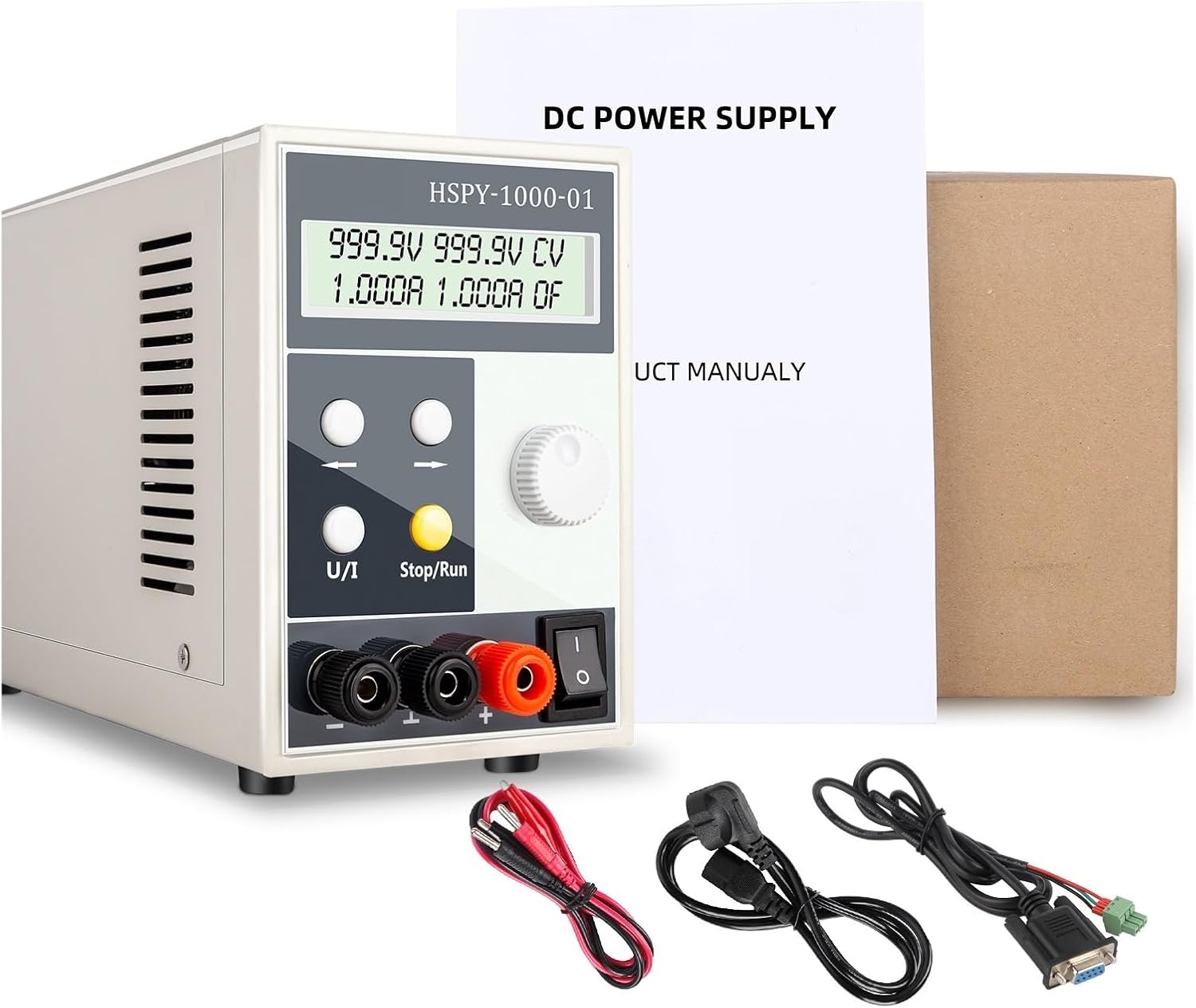
Figure 4.1: The power supply unit shown with its standard accessories, including power and output cables.
5. Operating Instructions
This section details how to operate your power supply for various applications.
Setting Voltage and Current:
- Enable Output: Press the Stop/Run button to enable the output. The display will show the current output status.
- Select Parameter: Press the U/I button to toggle between voltage (U) and current (I) adjustment modes. The active parameter will be highlighted or indicated on the display.
- Adjust Value: Use the Adjustment Knob to change the value of the selected parameter. Turn clockwise to increase, counter-clockwise to decrease. The knob allows for both fine and coarse adjustments.
- Fine Adjustment: For precise adjustments, use the Left and Right arrow buttons to select a specific digit on the display, then use the Adjustment Knob to change that digit.
- Confirm Settings: Once the desired voltage and current are set, the power supply will operate in either Constant Voltage (CV) or Constant Current (CC) mode, depending on the load.
Constant Voltage (CV) and Constant Current (CC) Modes:
- Constant Voltage (CV): When the load resistance is high enough that the set current limit is not reached, the power supply will maintain the set output voltage.
- Constant Current (CC): When the load resistance is low enough that the output current reaches the set current limit, the power supply will maintain the set output current, and the output voltage will drop accordingly.
6. Storage and Recall Memory Function
The power supply features three memory buttons to store and recall frequently used voltage and current settings.
- Storing Settings:
- Set the desired voltage and current using the adjustment knob and U/I button.
- Press and hold one of the memory buttons (e.g., M1, M2, or M3) for approximately 3 seconds until a confirmation message appears on the display, indicating the settings have been saved.
- Recalling Settings:
- Briefly press the desired memory button (e.g., M1, M2, or M3). The stored voltage and current values will be loaded and displayed.
- The output will automatically adjust to the recalled settings.
7. Maintenance
Proper maintenance ensures the longevity and reliable operation of your power supply.
- Cleaning: Disconnect the power supply from the AC outlet before cleaning. Use a soft, dry cloth to wipe the exterior. Do not use abrasive cleaners or solvents.
- Ventilation: Regularly check that the ventilation openings are free from dust and debris. A clogged fan can lead to overheating.
- Storage: If storing the unit for an extended period, ensure it is clean, dry, and stored in a stable environment away from extreme temperatures or humidity.
- Inspection: Periodically inspect the power cord and output cables for any signs of damage. Replace damaged cables immediately.
8. Troubleshooting
This section addresses common issues you might encounter with your power supply.
| Problem | Possible Cause | Solution |
|---|---|---|
| No power/Display off | Power cord not connected; Power switch off; Outlet fault. | Check power cord connection; Turn power switch ON; Test outlet with another device. |
| No output voltage/current | Output disabled (Stop mode); Incorrect settings; Overload protection activated. | Press Stop/Run to enable output; Verify voltage/current settings; Reduce load or check for short circuit. |
| Output voltage/current unstable | Loose connections; Faulty load; Internal fault. | Check all cable connections; Test with a different load; Contact support if issue persists. |
| Unit overheats / Fan constantly running | Blocked ventilation; Excessive load; High ambient temperature. | Ensure clear airflow around vents; Reduce load; Operate in a cooler environment. |
If the problem persists after attempting the above solutions, please contact customer support for assistance.
9. Specifications
Technical specifications for the PULME HSPY-400-1 DC Lab Switching Power Supply:
- Model: HSPY-400-1
- Input Voltage: 110 Volts AC
- Output Voltage Range: Up to 400V DC (specific range depends on model variant)
- Output Current Range: Up to 1A (specific range depends on model variant)
- Display: 4-digit LED (0.01V, 0.001A precision)
- Operating Modes: Constant Voltage (CV), Constant Current (CC)
- Memory Functions: 3 programmable storage/recall settings
- Material: Copper (internal components)
- Item Weight: Approximately 11.02 pounds (5000 Grams)
- Package Dimensions: 1.18 x 0.79 x 0.39 inches (Note: This appears to be incorrect for the actual unit size and may refer to a small component or packaging insert. Refer to Figure 3.3 for actual unit dimensions.)
Physical Dimensions:

Figure 9.1: Physical dimensions of the power supply unit.
10. Warranty and Support
PULME is committed to providing high-quality products. While specific warranty details are not provided in this manual, please retain your proof of purchase for any warranty claims. For technical support, troubleshooting assistance, or inquiries regarding your PULME HSPY-400-1 DC Lab Switching Power Supply, please contact your retailer or the manufacturer directly through their official support channels.