1. Product Overview
The DollaTek DC Buck Boost Converter is a versatile power module designed for precise voltage and current regulation. It features a digital LCD for real-time monitoring and offers a wide range of adjustable output parameters. This module is equipped with advanced protection mechanisms to ensure safe and reliable operation.
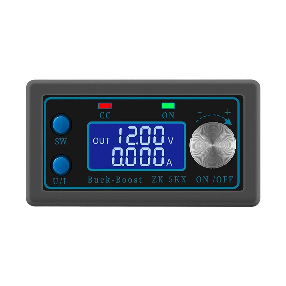
Figure 1.1: The DollaTek DC Buck Boost Converter with its clear liquid crystal display showing output voltage and current. The display provides precise and fast readings for monitoring.
2. Key Features
- LCD Display: Shows input/output voltage, output current/power, output capacity, and output time.
- Digital Control: Precise and fast adjustment of output voltage (0.6-36V) and current limit (0-5A).
- Input Reverse Polarity Protection: Prevents damage from incorrect input wiring.
- Comprehensive Software Protections: Adjustable thresholds for undervoltage, overvoltage, overcurrent, overpower, overtemperature, timed output, and overcapacity. Output automatically disables if thresholds are exceeded.
- Intelligent Temperature-Controlled Fan: Automatically starts when temperature exceeds 50°C or current exceeds 1A, ensuring efficient heat dissipation.
- Low Output Ripple: Features T-type filtration for stable output.
- Enhanced Heat Sink: Thicker heat sink with bidirectional ventilation for improved cooling performance.

Figure 2.1: Multiple views of the converter, highlighting its compact design and various components including the display, control buttons, and connection terminals.
3. Specifications
| Parameter | Value |
|---|---|
| Input Voltage | 6.0V - 36V |
| Output Voltage | 0.6V - 36V (Adjustable) |
| Output Current | Max 5A |
| Output Power | Max 80W |
| Voltage Display Resolution | 0.01V |
| Current Indicator Resolution | 0.001A |
| Conversion Efficiency | Approx. 88% |
| Soft Start | Yes (May fail with high power load) |
| Model Number | CP028911 |
| Dimensions (L x W x H) | 8 cm x 4.2 cm x 2.5 cm (approx.) |
| Manufacturer | DollaTek |
| Country of Origin | China |

Figure 3.1: Physical dimensions of the converter module.
4. Component Identification

Figure 4.1: Front panel controls and indicators. The 'SW' key switches display modes, 'U/I' key selects voltage/current adjustment, 'CC' indicates constant current mode, 'ON' indicates output enabled, and the rotary encoder adjusts values.

Figure 4.2: Internal components and connection points. The input terminals are labeled IN+ and IN-, while the output terminals are OUT+ and OUT-. The fan and heat sink are visible for thermal management.
5. Setup Instructions
- Power Off: Ensure all power sources are disconnected before making any connections.
- Input Connection: Connect your DC power source (6.0V-36V) to the IN+ and IN- terminals. Observe polarity: IN+ for positive, IN- for negative. The module has reverse polarity protection, but correct wiring is always recommended.
- Output Connection: Connect your load to the OUT+ and OUT- terminals. Observe polarity: OUT+ for positive, OUT- for negative.
- Secure Connections: Ensure all wire connections are tight and secure to prevent loose contacts and potential damage.
- Initial Power On: After verifying all connections, apply power to the input. The LCD display should illuminate.
6. Operating Instructions
6.1. Display Modes
- Press the SW key to cycle through different display modes: input voltage, output voltage, output current, output power, output capacity (Ah), and output time (h).
- The display will show 'IN' for input parameters and 'OUT' for output parameters.
6.2. Adjusting Output Voltage and Current
- Voltage Adjustment: Press the U/I key until the voltage value on the display starts blinking. Rotate the rotary encoder clockwise to increase the voltage and counter-clockwise to decrease it. Press U/I again to confirm the setting or wait a few seconds for it to auto-confirm.
- Current Limit Adjustment: Press the U/I key until the current value on the display starts blinking. Rotate the rotary encoder to set the desired current limit. Press U/I again to confirm. The 'CC' indicator will light up when the module operates in constant current mode.
6.3. Output Enable/Disable
- Press the ON/OFF button (often integrated with the rotary encoder or a separate button) to enable or disable the output. The 'ON' indicator light will show the output status.
7. Protection Mechanisms
The module incorporates several software protection features with adjustable thresholds. If any operating parameter exceeds its set threshold, the output will automatically be disabled to protect the module and the connected load.
- Input Anti-Reverse Protection: Prevents damage from incorrect input polarity.
- Output Anti-Reverse Protection: Protects the module if a reverse voltage is applied to the output.
- Input Undervoltage Protection (UVP): Adjustable from 5.8V to 36V (default 5.8V).
- Output Overvoltage Protection (OVP): Adjustable from 0.6V to 36V (default 36V).
- Output Overcurrent Protection (OCP): Adjustable from 0A to 5A (default 5A).
- Output Overpower Protection (OPP): Adjustable from 0W to 80W (default 80W).
- Overtemperature Protection (OTP): Adjustable from 80°C to 110°C (default 110°C).
- Timed Protection (OHP): Adjustable from 0 to 100 hours (default off).
- Overcapacity Protection (OAP): Adjustable from 0 to 60Ah (default off).
To adjust protection thresholds, refer to the detailed instructions provided with the product packaging or manufacturer's website, as the exact button sequence may vary slightly.
8. Maintenance
- Cleaning: Keep the module clean and free from dust. Use a soft, dry cloth for cleaning. Do not use liquids or abrasive cleaners.
- Ventilation: Ensure the fan and ventilation openings are not obstructed to maintain proper airflow and cooling. Periodically check for dust buildup on the fan blades and heat sink.
- Storage: Store the module in a dry, cool environment away from direct sunlight and extreme temperatures.
- Connections: Periodically check all electrical connections for tightness and signs of wear or corrosion.
9. Troubleshooting
- No Display/No Power:
- Check input power source and connections. Ensure input voltage is within 6.0V-36V.
- Verify correct input polarity.
- No Output:
- Ensure the output is enabled (check 'ON' indicator).
- Check for active protection (e.g., OVP, OCP, OTP indicators). If a protection is triggered, the output will be disabled. Address the cause (e.g., reduce load, check temperature) and re-enable output.
- Verify output connections and load.
- Output Voltage/Current Not Stable:
- Ensure input power is stable and sufficient for the desired output.
- Check for loose connections.
- If operating near maximum power (80W) or current (5A), ensure adequate cooling. The intelligent fan should activate.
- Fan Not Running:
- The fan is temperature-controlled. It will only activate if the internal temperature exceeds 50°C or the output current exceeds 1A. This is normal operation.
- If the module is hot and current is high, but the fan is not running, check for obstructions or fan malfunction.
10. Warranty and Support
Information regarding product warranty and customer support for the DollaTek DC Buck Boost Converter (Model CP028911) is not available in this manual. Please refer to the product packaging, the retailer's website, or contact DollaTek customer service directly for details on warranty coverage and technical assistance.
For further inquiries or support, please visit the official DollaTek website or contact your point of purchase.