1. Introduction
This manual provides detailed instructions for the installation, operation, and maintenance of your XikeStor SKS7300-12GPY2XGT2XGS 16 Port 2.5G L2 Managed Switch. This device is designed to enhance network capabilities with high-speed connectivity and advanced management features, suitable for various network environments.
2. Package Contents
Verify that all items listed below are included in your package. If any item is missing or damaged, please contact customer support.
- XikeStor SKS7300-12GPY2XGT2XGS 16 Port 2.5G L2 Managed Switch
- Power Supply
- User Manual
- Rack Mount Kit
- Console Cable
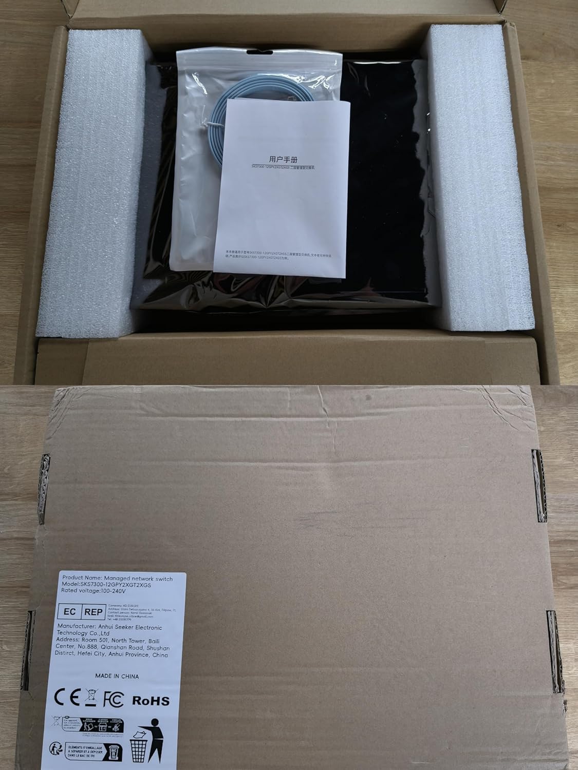
Image: Contents of the XikeStor switch package, including the switch unit, power supply, user manual, rack mount kit, and console cable.
3. Product Features
The XikeStor SKS7300-12GPY2XGT2XGS switch offers a robust set of features for advanced network management:
- High-Performance Connectivity: Equipped with 12x 2.5G RJ45 ports, 2x 10G RJ45 ports, and 2x 10G SFP+ ports for diverse high-speed network connections.
- Advanced Layer 2 Network Management: Provides comprehensive Layer 2 management capabilities via a user-friendly web interface and Command Line Interface (CLI), supporting VLAN segmentation, port aggregation, and mirroring.
- Efficient Cooling Design: Features built-in heatsinks and active fans, complemented by a metal casing and side ventilation holes, ensuring optimal heat dissipation and reliable operation.
- Versatile Installation Options: Supports both desktop placement and standard 19-inch rack-mounted configurations to suit various deployment needs.
- Durable and Sturdy Build: Constructed with a robust metal housing for enhanced longevity and stability in diverse operating environments.
4. Product Overview
4.1 Front Panel
Image: Front view of the XikeStor SKS7300-12GPY2XGT2XGS switch, showing all ports and LED indicators.
The front panel of the switch includes all network ports and LED indicators for monitoring device status and network activity.
- Ports 1-12: 2.5 Gigabit RJ45 ports for connecting standard Ethernet devices.
- Ports 13-14: 10 Gigabit RJ45 ports for high-speed copper connections.
- Ports 15-16: 10 Gigabit SFP+ slots for fiber optic connections.
- LED Indicators:
- PWR (Power): Indicates power status.
- SYS (System): Indicates system operational status.
- Link/Act LEDs (per port): Indicates link status and data activity for each port. Different colors or blinking patterns may denote connection speed (e.g., 100Mbps, 1Gbps, 2.5Gbps, 10Gbps). Refer to the specific LED legend on the device.
4.2 Rear Panel

Image: Rear view of the XikeStor SKS7300-12GPY2XGT2XGS switch, showing the power input and ventilation.
The rear panel contains the power input and ventilation openings.
- Power Input: Connector for the included power supply.
- Ventilation: Openings for airflow to ensure proper cooling of the device.
5. Setup Instructions
5.1 Safety Precautions
- Ensure the power source matches the voltage requirements of the switch.
- Do not block ventilation openings.
- Avoid placing the switch in direct sunlight, near heat sources, or in areas with high humidity.
- Use only the provided power supply.
5.2 Desktop Installation
Place the switch on a flat, stable surface. Ensure there is adequate space around the device for proper ventilation.
5.3 Rack-Mount Installation
To install the switch in a standard 19-inch equipment rack:
- Attach the provided rack-mount brackets to the sides of the switch using the included screws.
- Secure the switch into the rack using appropriate rack screws (not always included with the switch).
- Ensure the switch is level and securely fastened.
5.4 Power Connection
Connect the power supply cable to the power input port on the rear panel of the switch, then plug the other end into a suitable power outlet.
5.5 Network Connection
Connect your network devices (e.g., computers, servers, other switches) to the RJ45 ports using standard Ethernet cables. For fiber optic connections, insert compatible SFP+ modules into the SFP+ slots and connect fiber optic cables.
6. Operating Instructions
6.1 Power On/Off
Once the power supply is connected, the switch will automatically power on. To power off, disconnect the power supply from the outlet.
6.2 LED Indicators
Monitor the LED indicators on the front panel to understand the switch's status:
- PWR LED: Solid green indicates the device is powered on.
- SYS LED: Solid green indicates the system is operating normally. Blinking may indicate system activity or a specific status.
- Link/Act LEDs:
- Solid green: A stable link is established.
- Blinking green: Data is being transmitted or received on the port.
- Off: No link is detected or the port is inactive.
6.3 Management Access
The switch can be managed via a web-based graphical user interface (GUI) or a Command Line Interface (CLI).
- Web GUI: Connect a computer to any port on the switch. Configure your computer's IP address to be in the same subnet as the switch's default IP address (refer to the device label or documentation for the default IP). Open a web browser and enter the switch's IP address. Enter the default username and password (refer to the device label or documentation).
- CLI: Connect the console cable from your computer's serial port to the switch's console port. Use a terminal emulation program (e.g., PuTTY, Tera Term) with appropriate serial port settings (e.g., 115200 bps, 8 data bits, no parity, 1 stop bit, no flow control).
Once logged in, you can configure various Layer 2 features such as VLANs, port aggregation, QoS, and security settings.
7. Maintenance
7.1 Cleaning
Regularly clean the exterior of the switch with a soft, dry cloth. Do not use liquid or aerosol cleaners. Ensure ventilation openings are free from dust and debris to maintain optimal cooling.
7.2 Firmware Updates
Periodically check the XikeStor official website for firmware updates. Keeping the firmware up-to-date ensures optimal performance, security, and access to new features. Follow the instructions provided with the firmware update package carefully.
7.3 Environmental Considerations
Operate the switch within the specified temperature and humidity ranges to prevent damage and ensure stable performance.
8. Troubleshooting
This section addresses common issues you might encounter with the switch.
- No Power:
- Ensure the power cable is securely connected to both the switch and the power outlet.
- Verify the power outlet is functional.
- Check the PWR LED on the front panel. If it's off, try a different power cable or outlet.
- No Link on a Port:
- Check if the Ethernet cable is properly connected to both the switch port and the connected device.
- Ensure the connected device is powered on and functioning correctly.
- Try a different Ethernet cable.
- Verify the Link/Act LED for the specific port. If it's off, there might be an issue with the cable, device, or port.
- Slow Network Speed:
- Ensure all connected devices and cables support the desired speed (e.g., 2.5G or 10G).
- Check for excessive network traffic or bottlenecks elsewhere in the network.
- Verify the Link/Act LED color/pattern indicates the expected speed.
- Consider checking switch configurations for duplex settings or flow control.
- Cannot Access Web Management Interface:
- Ensure your computer's IP address is in the same subnet as the switch's IP address.
- Verify the switch's IP address is correct.
- Check for any firewall settings on your computer that might be blocking access.
- Try resetting the switch to factory defaults (refer to specific instructions for your model, usually involving a reset button).
9. Specifications
Detailed technical specifications for the XikeStor SKS7300-12GPY2XGT2XGS switch:
| Feature | Specification |
|---|---|
| Model | SKS7300-12GPY2XGT2XGS |
| Number of Ports | 16 (12x 2.5G RJ45, 2x 10G RJ45, 2x 10G SFP+) |
| Network Protocol Standards | IEEE 802.3, 802.3u, 802.3x, 802.3ab, 802.3z, 802.3bz, 802.3ad, 802.3an, 802.1Q, 802.1P |
| MAC Address Table Size | 16K (auto learning and update) |
| Transmission Mode | Store-and-forward |
| Jumbo Frame Support | 12KByte |
| Switching Capacity | 140Gbps |
| Packet Forwarding Rate | 104.16Mpps |
| Dimensions (L x W x H) | 335 x 218 x 43mm (13.19 x 8.58 x 1.69 inches) |
| Item Weight | 4.62 pounds |
| Operating Temperature | 0°C to 40°C (32°F to 104°F) |
| Storage Temperature | -10°C to 70°C (14°F to 158°F) |
| Operating Humidity | 10%-90% non-condensing |
| Storage Humidity | 5%-90% non-condensing |
| Case Material | Metal |
| Compatible Devices | Router, Desktop/Laptop |
10. Warranty and Support
For warranty information, technical support, or service inquiries, please refer to the warranty card included with your product or visit the official XikeStor website. You may also contact XikeStor customer support directly for assistance.