1. Introduction
The JDY-10 module is a Bluetooth 4.0 Low Energy (BLE) module designed for transparent data transmission via a Universal Asynchronous Receiver/Transmitter (UART) interface. It offers a simple and reliable solution for integrating Bluetooth connectivity into various embedded systems and applications. This module is compatible with the CC2541 Bluetooth chip architecture, providing stable performance and low power consumption.
This manual provides detailed instructions for setting up, operating, and maintaining your JDY-10 module, along with its specifications and troubleshooting tips.
2. Features
- Bluetooth 4.0 BLE standard compliant
- UART (Serial) interface for transparent data transmission
- Low power consumption
- Small form factor for easy integration
- Supports AT commands for configuration
- Compatible with CC2541 Bluetooth module architecture
3. Hardware Overview and Pinout
The JDY-10 module features a compact design with clearly labeled pins for easy connection to external circuits. Understanding the pinout is crucial for proper integration and operation.

Figure 1: Top view of the JDY-10 BLE Bluetooth module, showing the main chip and antenna trace.
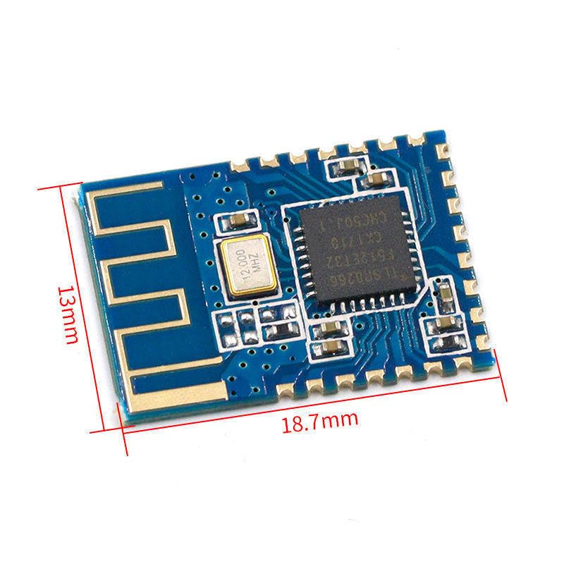
Figure 2: JDY-10 BLE Bluetooth module illustrating its physical dimensions: approximately 18.7mm in length and 13mm in width.
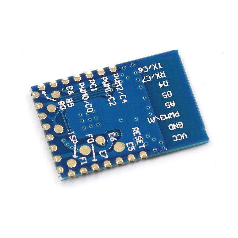
Figure 3: Bottom view of the JDY-10 BLE Bluetooth module, displaying the pin labels for connection.
3.1 Pin Description
| Pin | Name | Description |
|---|---|---|
| 1 | VCC | Power Supply (typically 1.8V - 3.6V) |
| 2 | GND | Ground |
| 3 | TX | UART Transmit (connect to RX of host microcontroller) |
| 4 | RX | UART Receive (connect to TX of host microcontroller) |
| 5 | STATE | Connection Status Indicator (High when connected, Low when disconnected) |
| 6 | EN | Enable Pin (High for normal operation, Low for sleep/disable) |
4. Specifications
| Parameter | Value |
|---|---|
| Model | JDY-10 |
| Bluetooth Version | Bluetooth 4.0 BLE |
| Hardware Interface | UART |
| Operating Voltage | 1.8V - 3.6V (Typical 3.3V) |
| Operating Current | ~8mA (Connected), <1mA (Sleep) |
| Communication Range | Up to 30 meters (line of sight) |
| Default Baud Rate | 9600 bps |
| Frequency Band | 2.4GHz ISM band |
| Dimensions | Approximately 18.7mm x 13mm |
5. Setup
Follow these steps to set up your JDY-10 module for initial use.
5.1 Powering the Module
- Connect the VCC pin to a stable power supply within the range of 1.8V to 3.6V. A 3.3V supply is typically recommended.
- Connect the GND pin to the ground of your power supply and host microcontroller.
5.2 UART Connection
To enable serial communication, connect the JDY-10 module to your host microcontroller (e.g., Arduino, ESP32) or a USB-to-UART converter as follows:
- JDY-10 TX pin → Host Microcontroller RX pin
- JDY-10 RX pin → Host Microcontroller TX pin
Ensure that the voltage levels of the UART communication match between the JDY-10 and your host device. If your host operates at 5V, a logic level converter may be required to prevent damage to the JDY-10 module.
5.3 Initial Configuration (AT Commands)
The JDY-10 module can be configured using AT commands sent via the UART interface. To enter AT command mode, ensure the module is powered on and connected to a serial terminal (e.g., PuTTY, Arduino Serial Monitor).
Common AT commands include:
- AT: Test command. Should return 'OK'.
- AT+NAME[name]: Set or query the Bluetooth device name. Example:
AT+NAMEJDY-BLE - AT+BAUD[baudrate]: Set or query the UART baud rate. Example:
AT+BAUD115200 - AT+PIN[pin]: Set or query the Bluetooth pairing password (if applicable). Example:
AT+PIN123456 - AT+VERSION: Query the firmware version.
After sending an AT command, the module typically responds with 'OK' or an error message. Refer to the specific JDY-10 AT command set documentation for a complete list and detailed usage.
6. Operating
Once configured, the JDY-10 module operates in transparent transmission mode, acting as a bridge between the UART and Bluetooth interfaces.
6.1 Bluetooth Connection
- Power on the JDY-10 module. The STATE pin may indicate its status (e.g., blinking when discoverable, solid when connected).
- On your host device (smartphone, computer, or another Bluetooth-enabled device), scan for Bluetooth Low Energy (BLE) devices.
- Locate the JDY-10 module by its configured name (default is often 'JDY-10' or similar).
- Initiate a connection. If a PIN is set, you will be prompted to enter it.
- Once connected, the STATE pin on the JDY-10 module will typically change its indication (e.g., stop blinking and remain solid).
6.2 Transparent Data Transmission
In transparent transmission mode, any data sent to the JDY-10's UART RX pin will be transmitted wirelessly over Bluetooth to the connected host device. Conversely, any data received by the JDY-10 via Bluetooth will be output through its UART TX pin.
- UART to Bluetooth: Data sent from your microcontroller's TX to the JDY-10's RX will appear on the connected Bluetooth device's serial terminal or application.
- Bluetooth to UART: Data sent from the connected Bluetooth device will be received by the JDY-10 and output from its TX pin to your microcontroller's RX.
Ensure that the baud rate of your host microcontroller's UART matches the configured baud rate of the JDY-10 module for reliable communication.
7. Maintenance
The JDY-10 module is a robust electronic component, but proper handling and care can extend its lifespan and ensure reliable operation.
- Handling: Avoid touching the module's components directly, especially the antenna trace, to prevent damage from electrostatic discharge (ESD) or contamination.
- Power Supply: Always provide a stable power supply within the specified voltage range (1.8V - 3.6V). Overvoltage can permanently damage the module.
- Environment: Operate the module in a clean, dry environment. Avoid exposure to extreme temperatures, humidity, or corrosive substances.
- Storage: When not in use, store the module in an anti-static bag in a cool, dry place.
8. Troubleshooting
If you encounter issues with your JDY-10 module, consider the following troubleshooting steps:
- Module Not Powering On:
- Verify VCC and GND connections are correct and within the specified voltage range.
- Check for any short circuits on the power lines.
- Not Visible in Bluetooth Scan:
- Ensure the module is powered on correctly.
- Check if the module is in AT command mode (it might not be discoverable in this mode).
- Verify the Bluetooth scanning device is BLE compatible.
- Ensure the module's antenna is not obstructed or damaged.
- Data Transmission Errors:
- Confirm that the UART baud rate of the JDY-10 matches the baud rate of your host microcontroller.
- Check TX/RX connections are not swapped.
- Verify logic level compatibility between the JDY-10 and your host microcontroller.
- Ensure the Bluetooth connection is stable (check STATE pin).
- AT Commands Not Responding:
- Ensure the serial terminal settings (baud rate, parity, stop bits) match the module's configuration.
- Verify that the AT commands are terminated correctly (e.g., with newline/carriage return, depending on module firmware).
9. Applications
The JDY-10 BLE module is suitable for a wide range of applications requiring low-power wireless serial communication, including:
- Internet of Things (IoT) devices
- Smart home automation
- Wearable electronics
- Remote control systems
- Data logging and monitoring
- Wireless sensor networks
10. Warranty and Support
Specific warranty information for the JDY-10 BLE Bluetooth 4.0 Uart Transparent Transmission Attachment is not provided in the product data. For details regarding warranty, returns, or technical support, please contact the seller or manufacturer directly through your purchase platform.