
1. Introduction
This manual provides essential information for the safe and efficient installation, operation, and maintenance of the Cotether 1204M-5201 Programmable DC Series Motor Controller. Read this manual thoroughly before attempting to install or operate the controller. Retain this manual for future reference.
Safety Precautions
- Always disconnect power before performing any installation, maintenance, or troubleshooting.
- Ensure all wiring connections are secure and correct to prevent damage to the controller or vehicle.
- This device operates with high voltage and current. Only qualified personnel should perform installation and service.
- Wear appropriate personal protective equipment (PPE) during installation and maintenance.
2. Product Overview
The Cotether 1204M-5201 is a programmable DC series motor controller designed for various electric vehicle applications. It features robust construction and supports multiple throttle input types for versatile integration.

Figure 1: Cotether 1204M-5201 DC Series Motor Controller, front-side view showing terminals and heat sink fins.
Key Features
- Part Number: 1204M-5201
- Voltage Compatibility: 36-48V (exact voltage required for configuration)
- Current Rating: 275A
- Programmable for various throttle types.
3. Specifications
| Parameter | Value |
|---|---|
| Model Number | 1204M-5201 |
| Operating Voltage | 36-48V DC (specific voltage required for configuration) |
| Current Rating | 275A |
| Throttle Input Types | 10 configurable types (e.g., 0-5kΩ, 5kΩ-0, 0-5V, ITS) |
| Color | Black |
| Included Components | Motor Controller |
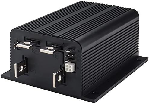
Figure 2: Product dimensions for the Cotether 1204M-5201 controller, showing measurements in millimeters.
4. Setup and Installation
Proper installation is crucial for the controller's performance and longevity. Ensure the mounting location provides adequate ventilation and protection from environmental elements.
Wiring Diagram

Figure 3: General wiring diagram for the Cotether 1204M-5201 DC Series Motor Controller, illustrating connections for battery, motor, throttle, and control circuits.
Installation Steps
- Mounting: Securely mount the controller in a location that minimizes vibration and allows for proper heat dissipation.
- Battery Connections: Connect the main battery positive (B+) and negative (B-) terminals to the corresponding terminals on the controller. Ensure correct polarity and use appropriately sized cables.
- Motor Connections: Connect the motor armature (A1, A2) and field (F1, F2) terminals to the controller as indicated in the wiring diagram.
- Throttle Connection: Connect your vehicle's throttle to the controller. Important: The controller requires specific configuration for your throttle type. Contact the seller post-purchase to specify your vehicle's throttle type from the 10 available options.
- Voltage Configuration: The controller requires an exact voltage value for configuration. Please confirm your vehicle's operating voltage (e.g., 36V or 48V) and communicate this to the seller after purchase for proper setup.
- Control Wiring: Connect keyswitch, interlocks, and pedal microswitch as per the wiring diagram. Install appropriate fuses for control and power circuits.
- Initial Check: Before applying full power, double-check all connections for tightness and correct routing.
5. Operating Instructions
Once installed and configured, the controller manages the motor's speed and torque based on the throttle input.
Throttle Types
The controller supports ten different throttle types. It is crucial that the controller is configured to match your vehicle's specific throttle. The available types include:
- Type 0: 2-wire potentiometer, 0-5kΩ
- Type 1: 2-wire potentiometer, 5kΩ-0
- Type 2: Single-ended 0-5V input
- Type 3: 2-wire potentiometer, 4.6kΩ-0
- Type 4: 2-wire potentiometer, 5.5kΩ-0
- Type 5: 2-wire potentiometer, 1kΩ-0
- Type 6: ITS input
- Type 7: Single-ended 6.3-10.6V input
- Type 8: Single-ended 6-12V input
- Type 9: Single-ended 3-wire potentiometer, 0-5kΩ
Ensure your controller has been pre-configured for the correct throttle type before operation. If unsure, contact the seller.
Initial Power-Up
- With all connections verified, turn the keyswitch to the ON position.
- Observe any status indicators on the controller or vehicle dashboard.
- Slowly depress the throttle to confirm proper motor response.
6. Maintenance
Regular maintenance helps ensure the longevity and reliable operation of your motor controller.
- Visual Inspection: Periodically inspect the controller for any signs of physical damage, corrosion, or loose connections.
- Cleaning: Keep the controller free from dust, dirt, and moisture. Use a dry, soft cloth for cleaning. Do not use solvents or abrasive cleaners.
- Connection Checks: Ensure all power and control wiring connections remain tight and free from wear.
- Ventilation: Verify that the controller's heat sink fins are not obstructed, allowing for proper airflow and cooling.
7. Troubleshooting
If the controller or motor system is not functioning as expected, perform the following basic checks:
- No Power: Check battery voltage, main fuse, and keyswitch operation. Ensure all power connections are secure.
- Motor Not Responding: Verify throttle connections and ensure the throttle type is correctly configured for the controller. Check motor connections and brushes.
- Erratic Operation: Inspect all wiring for loose connections or damage. Ensure the controller is receiving the correct voltage and throttle signal.
- Overheating: Check for obstructions around the controller's heat sink. Ensure the motor is not overloaded.
For complex issues or if basic troubleshooting does not resolve the problem, contact technical support.
8. Warranty and Support
For information regarding warranty coverage, terms, and conditions, please refer to the product's purchase documentation or contact the seller directly. Technical support is available to assist with installation, operation, and troubleshooting queries.
Contact Information: Please refer to your purchase receipt or the seller's contact details provided at the time of purchase for support.