Product Overview
The Greluma W3230 Digital Temperature Controller is a versatile device designed for precise temperature management. It features a digital display for real-time temperature monitoring and a relay output for controlling heating or cooling equipment. This controller is suitable for a wide range of applications, including HVAC systems, freezers, refrigerators, fermentation chambers, and more, where automatic temperature switching is required.

Image: Two Greluma W3230 Digital Temperature Controllers. Each unit features a digital LED display showing current (PV) and set (SV) temperatures, along with control buttons and a connected NTC 10K temperature sensor.
Key features include temperature calibration, high/low temperature alarm settings, and the ability to switch between heating and cooling modes. Its robust design with a 10A relay output can handle various high-power loads, ensuring reliable operation.
Setup and Wiring
Before operating the device, ensure proper wiring according to the diagram below. Incorrect wiring can damage the unit or connected equipment.
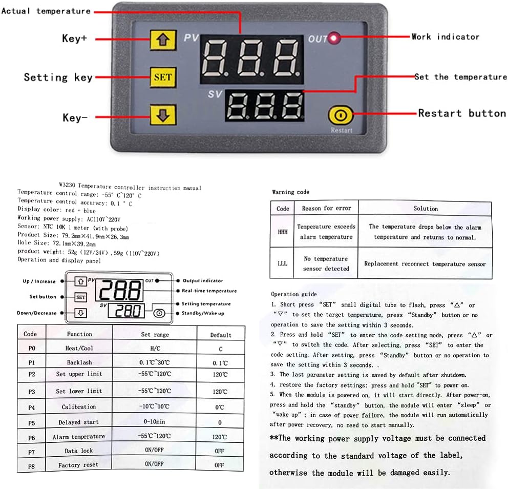
Image: Detailed diagram showing the Greluma W3230 temperature controller's wiring terminals (+VCC, -GND, S1, S2 for sensor, and Load connections) and the front panel layout with buttons and display indicators.
- Power Connection: Connect the AC 110V-220V power supply to the designated terminals (+VCC and -GND). Refer to the wiring diagram for correct polarity.
- Load Connection: Connect your heating or cooling load (e.g., heater, fan, compressor) to the "Load" terminals. The output is a 10A relay. Ensure the load's power requirements do not exceed the relay's capacity.
- Sensor Connection: Connect the NTC 10K temperature sensor to the S1 and S2 terminals. Ensure the sensor is properly installed in the environment where temperature measurement is required. If the sensor is missing or damaged, the display will show "-- --".
Important: Always disconnect power before performing any wiring or maintenance. Ensure all connections are secure to prevent short circuits.
Operating Instructions
The W3230 controller features a clear digital display and intuitive button controls.
Display and Indicators
- PV (Process Value): The upper digital display shows the current measured temperature.
- SV (Set Value): The lower digital display shows the set target temperature.
- OUT (Output Indicator): A small LED indicator. When lit, the relay is closed (output is active). When off, the relay is disconnected (output is inactive).
Button Functions
- ▲ (Up/Increase) Key: Increases the value during setting.
- ▼ (Down/Decrease) Key: Decreases the value during setting.
- SET Key:
- Short Press: Enters the set temperature adjustment mode. The SV display will flash. Use ▲ and ▼ to adjust the target temperature. Press SET again or wait 3 seconds for the setting to save.
- Long Press (3 seconds): Enters the parameter setting mode (P0-P8). The PV display will show the parameter code (e.g., "P0"). Use ▲ and ▼ to navigate between parameters. Press SET again to enter the selected parameter's value adjustment. Use ▲ and ▼ to change the value. Press SET again to save the parameter value and return to parameter selection, or long press SET for 3 seconds to exit.
- Restart Button: A small recessed button (often requires a pointed object to press). Restarts the device.
Parameter Settings (P0-P8)
To access these advanced settings, long press the SET button for 3 seconds. Use the Up/Down keys to select the parameter, then press SET to modify its value. Press SET again to confirm and exit the parameter, or long press SET to exit the entire setting mode.
| Code | Function | Set Range | Default |
|---|---|---|---|
| P0 | Heating/Cooling Mode | H/C | C (Cooling) |
| P1 | Return Difference (Hysteresis) | 0.1-15 | 2 |
| P2 | Setting Upper Limit | -55°C to 120°C | 120°C |
| P3 | Setting Lower Limit | -55°C to 120°C | -50°C |
| P4 | Temperature Correction (Calibration) | -7.0°C to 7.0°C | 0°C |
| P5 | Delay Start Time | 0-10 minutes | 0 minutes |
| P6 | High Temperature Alarm | -55°C to 120°C | OFF |
| P7 | Data Lock | ON/OFF | OFF |
| P8 | Factory Reset | ON/OFF | OFF |
Note: The "Code table" and "Operation guide" from the product images (e.g., 71bc3SO35iL._AC_SL1000_.jpg) were used to compile this information.
Maintenance
To ensure the longevity and accurate operation of your Greluma W3230 temperature controller, follow these maintenance guidelines:
- Cleaning: Gently wipe the unit with a soft, dry cloth. Do not use abrasive cleaners or solvents, as they may damage the display or casing.
- Sensor Care: Keep the temperature sensor clean and free from debris. Avoid bending or damaging the sensor probe. Ensure it is securely placed in the measurement area.
- Environmental Conditions: Operate the controller within the specified environmental requirements (-10°C to 60°C, 20%-85% RH humidity) to prevent malfunction.
- Connection Check: Periodically inspect all wiring connections to ensure they remain tight and free from corrosion.
Troubleshooting
This section addresses common issues you might encounter with your temperature controller.
| Warning Code / Symptom | Reason for Error | Solution |
|---|---|---|
| Display shows "-- --" | Temperature sensor is missing or damaged. | Check if the temperature sensor is properly connected. If connected, the sensor may be faulty and require replacement. |
| Display shows "HHH" | Temperature exceeds the alarm temperature (P6 setting). | The temperature has risen above the set high temperature alarm threshold. The relay will automatically disconnect in heating mode. Allow the temperature to drop or adjust the P6 setting. |
| Display shows "LLL" | No temperature sensor detected. | Similar to "-- --", this indicates a sensor issue. Reconnect or replace the temperature sensor. The relay will automatically disconnect in refrigeration mode. |
| Controller not powering on | No power supply or incorrect wiring. | Verify the AC 110V-220V power supply is connected correctly to the +VCC and -GND terminals. Check for loose connections or power outages. |
| Output (relay) not activating | Temperature not within set range, P5 delay active, or P7 data lock active. | Ensure the current temperature (PV) is outside the set temperature (SV) plus/minus hysteresis (P1) to trigger the relay. Check P5 (delay start) setting. Verify P7 (data lock) is OFF if you need to change settings. |
Specifications
| Feature | Detail |
|---|---|
| Model | W3230 |
| Input Voltage | AC 110V-220V |
| Temperature Control Range | -50°C to 110°C (-58°F to 230°F) |
| Control Accuracy | 0.1°C |
| Measurement Input | NTC 10K / B3435 (1M Waterproof Probe) |
| Output Capacity | 1 Channel Relay Output, 20A |
| Environmental Requirements | Temperature: -10°C to 60°C; Humidity: 20%-85% RH |
| Dimensions (L x W x H) | 79mm x 43mm x 26mm (approx. 3.11" x 1.69" x 1.02") |
| Mounting Hole Size | 72mm x 39mm (approx. 2.83" x 1.54") |
| Weight | 90 grams |
| Display Type | LED Digital Display (Red/Blue) |
| Material | Plastic |

Image: Diagram illustrating the physical dimensions of the Greluma W3230 controller in millimeters and inches, along with a simplified wiring schematic for power and load connections.
Warranty and Support
Specific warranty information for the Greluma W3230 Digital Temperature Controller is not provided in this manual. Please refer to your purchase documentation or contact the retailer/manufacturer directly for warranty details and support inquiries.
For technical assistance or further questions, please reach out to Greluma customer support through their official channels.


