1. Introduction
This manual provides detailed instructions for the safe and efficient operation of the Generic 600W DC-DC Boost Converter Step-up Module. This module is designed to convert a lower DC input voltage (10V-60V) into a higher, continuously adjustable DC output voltage (12V-80V), suitable for various electronic applications requiring a step-up voltage conversion.
2. Safety Information
Please read and understand all safety warnings before operating this device. Failure to follow these instructions may result in electric shock, fire, or damage to the module or connected equipment.
- High Voltage and Current: This module operates with high voltages and currents. Exercise extreme caution during installation and operation. Always ensure power is disconnected before making any connections or adjustments.
- Proper Insulation: Ensure all connections are properly insulated to prevent short circuits.
- Heat Dissipation: The module generates heat during operation, especially at higher power levels. Ensure adequate ventilation and consider additional cooling if operating near maximum current.
- Polarity: Always observe correct input and output polarity. Incorrect connections can damage the module and connected devices.
- Professional Installation: If you are unfamiliar with electronic circuits, seek assistance from a qualified professional.
- Indoor Use: This module is intended for indoor use in a dry environment. Avoid exposure to moisture or extreme temperatures.
3. Product Overview
The 600W DC-DC Boost Converter module features robust components designed for stable voltage step-up. It includes input and output terminals, potentiometers for voltage and current adjustment, and an integrated heat sink for thermal management.
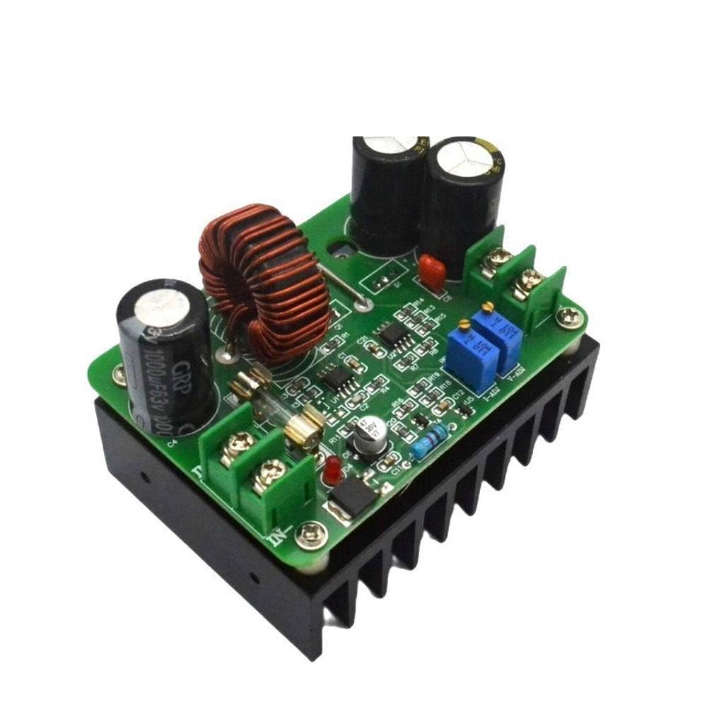
Figure 3.1: Overall view of the 600W DC-DC Boost Converter module.
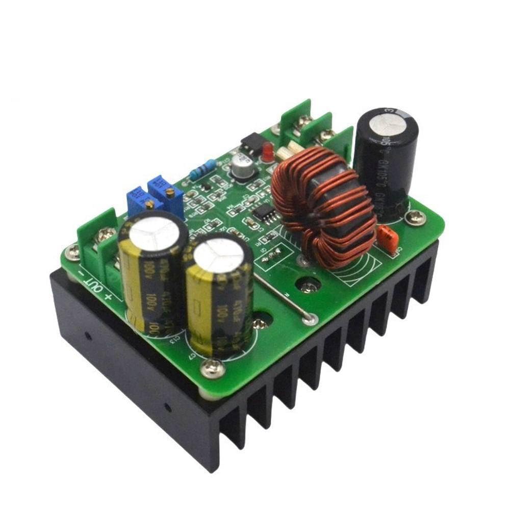
Figure 3.2: Top-down view highlighting input and output terminals.

Figure 3.3: View showing voltage and current adjustment potentiometers.

Figure 3.4: Bottom view with integrated heat sink.
4. Specifications
| Parameter | Value |
|---|---|
| Input Voltage | 10V - 60V DC |
| Input Current | 15A (Maximum), strengthen heat dissipation above 10A |
| Output Voltage | 12V - 80V DC (Continuously Adjustable) |
| Output Current | 10A (Maximum), strengthen heat dissipation above 10A |
| Output Power | Input Voltage * 10A (e.g., 12V*10A=120W, 60V*10A=600W) |
| Conversion Efficiency | Up to 95% (efficiency varies with input/output voltage, current, and differential pressure) |
| Operating Frequency | 150KHz |
| Operating Temperature | -40°C to +85°C (strengthen heat dissipation if ambient temperature is high) |
| Module Nature | Non-isolated boost module (BOOST) |
| Short-circuit Protection | Yes (Input 20A fuse, double short-circuit protection) |
| Over-current Protection | Yes (Input over 17A automatically reduces output voltage, with a certain error range) |
| Input Reverse Protection | None |
| Module Size | 73mm * 51mm |
| Weight | 265g |
5. Setup and Installation
- Prepare Connections: Ensure all power sources are disconnected before making any connections. Use appropriate gauge wires for the expected current.
- Input Connection: Connect your DC input power source to the IN+ (positive) and IN- (negative) terminals. Observe correct polarity.
- Output Connection: Connect your load or device to the OUT+ (positive) and OUT- (negative) terminals. Observe correct polarity.
- Heat Dissipation: For continuous operation at high currents (above 10A input or output), ensure the module has sufficient airflow. Additional cooling, such as a fan, may be required to prevent overheating.
- Parallel Operation (Optional): For applications requiring higher output current (e.g., 15A), two modules can be used in parallel. In such cases, adjust the current limit of each module to approximately half of the total desired current (e.g., 8A per module for a 15A total output).
6. Operating Instructions
After completing the setup, you can power on the module and adjust the output voltage and current.
- Power On: Connect the input power source.
- Voltage Adjustment: Use a multimeter to monitor the output voltage. Turn the V-ADJ potentiometer (typically the one closer to the output terminals) clockwise to increase the output voltage and counter-clockwise to decrease it. Adjust to your desired voltage.
- Current Adjustment: To set the output current limit, connect a suitable load or a current meter in series with the output. Turn the I-ADJ potentiometer (typically the one closer to the input terminals) clockwise to increase the current limit and counter-clockwise to decrease it. Note: Do not short-circuit the output to adjust the current limit on a boost converter, as this can damage the module. Always adjust with a load connected.
7. Maintenance
This module requires minimal maintenance. Keep the module clean and free from dust and debris. Ensure proper ventilation to prevent overheating. Regularly check connections for tightness and signs of wear or corrosion.
8. Troubleshooting
- No Output Voltage:
- Check input power supply and ensure it is within the specified range (10V-60V).
- Verify all input and output connections for correct polarity and secure contact.
- Check the input fuse for continuity.
- Output Voltage is Lower Than Expected:
- Ensure the input voltage is sufficient for the desired output voltage.
- Check if the current limit (I-ADJ) is set too low for the connected load.
- Verify the load is not drawing excessive current, causing the module to enter over-current protection.
- Module Overheating:
- Reduce the output current or power.
- Improve ventilation around the module. Consider adding a cooling fan.
- Ensure the ambient temperature is within the operating range.
9. Applications
This versatile boost converter module can be used in various applications, including:
- DIY regulated power supplies.
- Solar panel voltage boosting for battery charging.
- Battery charging applications (e.g., boosting 12V to charge 24V or 48V batteries).
- High-power LED drivers.
- Automotive power conversions.
10. Warranty and Support
This product is provided by Generic. For any technical support, warranty claims, or inquiries, please contact the seller or manufacturer directly through your purchase platform. Please retain your proof of purchase for warranty purposes.


