1. Introduction and Overview
This manual provides essential information for the safe and effective installation, operation, and maintenance of your ATO 32 Amp AC Contactor, model 24V AC 3 NO. An AC contactor is an electrically controlled switch used for switching an electrical power circuit. This specific model features a mechanical interlock, designed for reliable performance in various industrial and commercial applications.
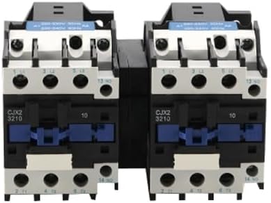
Image 1.1: Front view of the ATO 32 Amp AC Contactor. This image displays the main body of the contactor with terminals and control elements visible.
2. Safety Information
Always observe the following safety precautions to prevent injury or damage to the equipment:
- Ensure power is disconnected before installation, wiring, or maintenance.
- Installation and wiring should only be performed by qualified personnel.
- Verify correct voltage and current ratings before connecting to a circuit.
- Do not operate the contactor if it appears damaged.
- Protect the contactor from moisture and extreme temperatures.
3. Product Features
The ATO 32 Amp AC Contactor is designed with several key features for reliable operation:
- Mechanical Interlock: Equipped with a mechanical interlock and two reversing contactors for enhanced safety and control in switching electrical power circuits.
- Energy Efficiency: Designed to save electric energy.
- Noise Reduction: Helps eliminate power frequency noise during operation.
- Robust Construction: Features silver contacts, 32 iron cores, and a pure copper coil for durability and performance.

Image 3.1: Diagram illustrating key internal components and features such as silver contacts, 32 iron cores, and a pure copper coil, contributing to the contactor's performance.
4. Specifications
| Parameter | Value |
|---|---|
| Coil Rated Voltage | 24V AC |
| Contact Form | 3 NO (Normally Open) |
| Rated Current | 32 Amp |
| Dimensions (approx.) | 168 x 86 x 100mm (Length x Width x Height) |
| Weight | 1.5kg |
| DIN Rail Size | 35mm |
| Included Components | 1 Mechanical Interlock Contactor |

Image 4.1: Dimensional drawing of the ATO 32 Amp AC Contactor, showing approximate measurements of 168mm length, 86mm width, and 100mm height.
5. Setup and Installation
The contactor is designed for mounting on a standard 35mm DIN rail. Follow these general steps for installation:
- Power Disconnection: Ensure all power to the circuit is completely disconnected at the main breaker before beginning installation.
- Mounting: Securely attach the contactor to a 35mm DIN rail in an appropriate electrical enclosure.
- Wiring: Connect the main power circuit to the appropriate power terminals (L1, L2, L3 for input; T1, T2, T3 for output). Connect the control circuit (24V AC) to the coil terminals (A1, A2). Refer to the wiring diagram on the unit for specific terminal identification.
- Verification: Double-check all connections for tightness and correctness according to the circuit diagram.
- Enclosure: Close and secure the electrical enclosure.
- Power Restoration: Restore power and test the contactor's operation.
6. Operating Instructions
The ATO AC Contactor operates by energizing its coil, which creates a magnetic field to close the main contacts, thereby completing the power circuit. When the coil is de-energized, the contacts open, breaking the circuit.
- Activation: Apply the rated control voltage (24V AC) to the coil terminals (A1, A2) to activate the contactor. The main contacts will close.
- Deactivation: Remove the control voltage from the coil terminals to deactivate the contactor. The main contacts will open.
- Mechanical Interlock: The mechanical interlock ensures that only one of the two reversing contactors can be closed at any given time, preventing short circuits in reversing motor applications.
7. Applications
This AC magnetic reversing contactor with mechanical interlock is suitable for use in circuits with rated voltages from 24V to 380V AC (50Hz or 60Hz) for various applications, including:
- AC-1 Category: Resistance furnaces, incandescent lamps, electric heaters.
- AC-3 Category: Air conditioners, compressors, fans.
- Motor Control: Ideal for controlling motors and compressors in heating, ventilation, air conditioning, and refrigeration (HVAC) systems, as well as food service equipment.

Image 7.1: Illustrative icons suggesting common applications such as temperature control, time control, and water level control, where this contactor can be utilized.
8. Maintenance
Regular maintenance helps ensure the longevity and reliable operation of your AC contactor:
- Inspection: Periodically inspect the contactor for any signs of physical damage, loose connections, or excessive wear.
- Cleaning: Keep the contactor free from dust, dirt, and foreign matter. Use a dry, soft cloth for cleaning. Do not use solvents.
- Terminal Tightness: Check and tighten all terminal screws as necessary to ensure good electrical contact.
- Contact Condition: If accessible and safe to do so, inspect the contacts for pitting or carbon buildup. Replace the contactor if contacts are severely worn or damaged.
9. Troubleshooting
Refer to the following common issues and their potential solutions:
Issue: Contactor produces noise during operation.
Possible Causes and Solutions:
- Insufficient Power Supply Voltage: Ensure the control voltage to the coil is within the specified range (24V AC). Low voltage can lead to insufficient electromagnet suction.
- Improper Assembly or Vibration: Check if the magnetic system is properly assembled and free from vibration. Ensure no parts are stuck, preventing the core from fully closing.
- Foreign Matter on Pole Surface: Inspect the pole surface for rust or foreign matter (e.g., grease, dust, hair). Clean if necessary.
- Excessive Contact Spring Pressure: If contact spring pressure is too high, it can cause noise. This typically requires professional adjustment or replacement.
- Short Circuit Ring Break: A broken short circuit ring can cause humming. This requires replacement of the contactor.
- Excessive or Uneven Iron Core Pole Wear: Worn iron core poles can lead to improper seating and noise. Replace the contactor if wear is significant.
Issue: Contactor contacts overheat or burn during prolonged operation.
Possible Causes and Solutions:
- Insufficient Contact Spring Pressure: Increase the contact spring pressure if possible, or replace the contactor if the spring is weak.
- Contaminated or Uneven Contact Surface: Clean the contact surface if there is oil or unevenness. Ensure metal particles are not prominent.
- High Ambient Temperature or Enclosed Space: Ensure adequate ventilation if operating in a high ambient temperature or a closed control box. Consider derating the contactor if conditions are severe.
- Excessive Load for Copper Contacts: If copper contacts are used for long-term heavy loads, they may overheat. Ensure the contactor is appropriately rated for the application.
- Insufficient Contact Overtravel: Adjust the contact overtravel if possible, or replace the contactor if the overtravel is too small.
10. Warranty and Support
ATO is committed to providing quality products and customer satisfaction. For any technical assistance regarding product selection, wiring, commissioning, or any other issues, please contact ATO professional engineers. Free technical support is available to ensure you get the most out of your product.
For specific warranty details, please refer to the documentation included with your purchase or visit the official ATO website.