1. Introduction
The MokerLink 8 Port 2.5G Ethernet Managed Switch with 1 Port 10G Ethernet Uplink is a high-performance networking device designed to enhance your network's speed and efficiency. It features 8 x 2.5G Base-T ports and a 1 x 10G Ethernet Uplink port, supporting adaptive speeds from 10/100/1000Mbps to 2.5G and 1G/2.5G/5G/10G respectively. This switch offers both unmanaged and web-managed modes, providing flexibility for various network environments, from home entertainment to office setups.
2. Key Features
- 2.5G/10G Ports: 8 x 2.5Gigabit Ethernet Ports (IEEE802.3bz compliant) supporting 10/100/1000M/2.5G adaptive speeds, and 1x 10G Ethernet Uplink Port (1G/2.5G/5G/10G compliant) for higher uplink rates. Features a 60Gbps backplane bandwidth for excellent data forwarding.
- Web GUI Managed: Supports device/port status query and various L2 configurations including VLAN, QoS, security, multicast, MAC address table, and diagnosis.
- Metal Fanless Design: Durable metal casing with a fanless design for lower energy consumption, quiet operation, and stable performance.
- Easy to Maintain: Power and port LED indicators clearly display running status and port rate, simplifying installation and maintenance.
- Widely Used: Compact size with desktop/wall-mounting design, suitable for various environments such as home entertainment, offices, 4K video streaming, gaming PCs, NAS, PCIe Adapters, Servers, and WiFi 6 APs.
3. Package Contents
Verify that all items are present in your package:
- MokerLink 8 Port 2.5G Ethernet Managed Switch
- Power Adapter (12V / 1.5A)
- Power Cord
- User Manual (this document)
4. Product Overview
4.1 Front Panel

Figure 4.1: Front view of the MokerLink 8 Port 2.5G Ethernet Managed Switch, showing all 8 x 2.5G ports, 1 x 10G uplink port, PWR LED, and the U/M mode switch.
- Ports 1-8 (2.5G/1G/100M/10M): Eight 2.5 Gigabit Ethernet ports. Each port has an LED indicator: Green for 2.5G/1G link, Yellow for 100M/10M link.
- Port 9 (10G/5G/2.5G/1G): One 10 Gigabit Ethernet Uplink port. This port supports higher speeds for connecting to a core switch or server.
- PWR LED: Indicates power status. Green when powered on, off when powered off.
- U/M Switch: Toggles between Unmanaged (U) and Web Managed (M) modes.
- Reset Button: Short press to restart the device. Long press (5 seconds) to restore factory settings.
4.2 Rear Panel
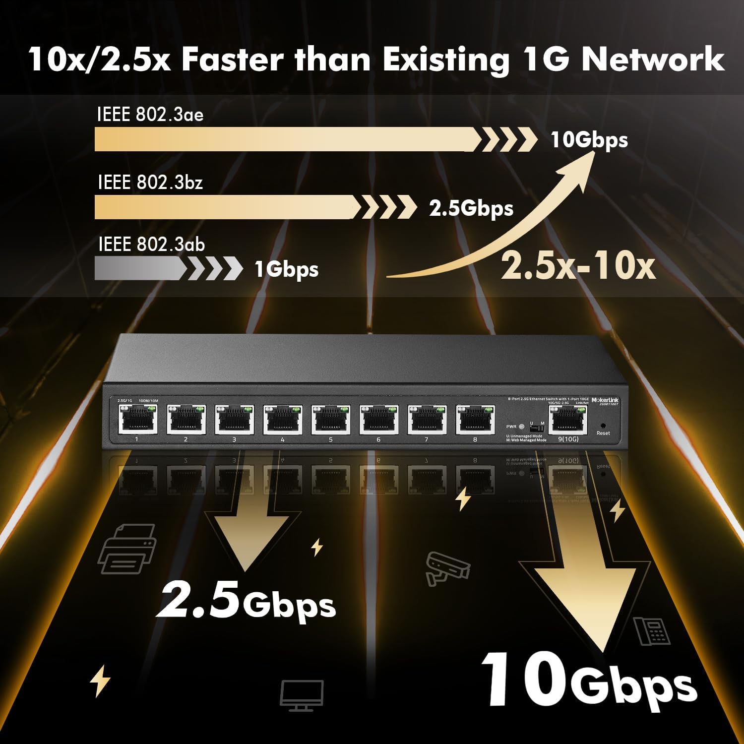
Figure 4.2: Rear view of the MokerLink 8 Port 2.5G Ethernet Managed Switch, showing the DC power input and grounding screw.
- DC Input Port: Connect the provided 12V/1.5A power adapter here.
- Grounding Screw: For connecting a grounding wire to ensure electrical safety.
5. Setup
5.1 Initial Connection
- Power Connection: Connect the provided power adapter to the DC input port on the rear panel of the switch and plug it into a power outlet. The PWR LED on the front panel should illuminate.
- Network Device Connection: Connect your network devices (e.g., computers, NAS, WiFi 6 APs, gaming PCs) to ports 1-8 using standard Ethernet cables (CAT5e, CAT6, CAT6a, or CAT7).
- Uplink Connection: Connect the 10G uplink port (Port 9) to your router, server, or core switch for network access. For 10G connections, use CAT6a or CAT7 cables for optimal performance over longer distances.
- Mode Selection: Ensure the U/M switch on the front panel is set to your desired operating mode (Unmanaged or Web Managed).

Figure 5.1: Example network setup with the MokerLink switch connecting various devices.
6. Operating Modes
The MokerLink switch supports two operating modes, selectable via the U/M switch on the front panel:

Figure 6.1: Switching between Unmanaged and Web Managed modes.
6.1 Unmanaged Mode (U)
In Unmanaged Mode, the switch operates as a plug-and-play device. No configuration is required. Simply connect your devices, and the switch will automatically handle data forwarding. This mode is ideal for basic network expansion without the need for advanced features.
6.2 Web Managed Mode (M)
In Web Managed Mode, the switch provides access to a web-based Graphical User Interface (GUI) for advanced configuration and monitoring. This mode allows you to utilize features such as VLAN, QoS, Link Aggregation, and more, giving you greater control over your network traffic.
7. Advanced Features (Web Managed Mode)
To access the web management interface, ensure the U/M switch is set to 'M' (Web Managed Mode).
7.1 Web GUI Access
- Connect a computer to any port of the switch.
- Configure your computer's IP address to be in the same subnet as the switch's default IP address (e.g., if the switch is 192.168.2.1, set your computer to 192.168.2.X, where X is not 1).
- Open a web browser and enter the default IP address of the switch: 192.168.2.1
- Enter the default login credentials:
Username: admin
Password: admin

Figure 7.1: Web management interface for configuration and monitoring.
7.2 VLAN (Virtual Local Area Network)
VLANs allow you to segment your network into smaller, isolated broadcast domains. This enhances network security and performance by limiting broadcast traffic and controlling access between different network segments. The switch supports 802.1Q Tag-based VLANs.

Figure 7.2: VLANs create virtual boundaries to segregate networks.
7.3 QoS (Quality of Service)
QoS prioritizes network traffic to ensure critical applications (like voice or video) receive sufficient bandwidth, reducing latency and packet loss. This is essential for maintaining smooth performance for real-time services.

Figure 7.3: QoS provides different priorities to applications.
7.4 Link Aggregation (LACP)
Link Aggregation (LACP) combines multiple physical Ethernet links into a single logical link. This increases bandwidth and provides redundancy, improving the resilience and performance of your network connections.

Figure 7.4: Link Aggregation increases bandwidth and resilience.
7.5 Loop Detection
Loop Detection helps identify and prevent network loops, which can cause broadcast storms and bring down your network. This feature ensures network stability by detecting and mitigating such issues.

Figure 7.5: Loop Detection helps identify and remove loops on your network.
7.6 Other L2 Features
The switch also supports other Layer 2 management features, including:
- IGMP Snooping
- Mirroring
- Jumbo Frame support (up to 12Kbytes)
- MAC Constraint
- Firmware Backup and Upgrade
8. Specifications
| Attribute | Value |
|---|---|
| Model Number | 8x2.5G +10G Managed |
| Switch Type | Managed |
| Number of Ports | 8 x 2.5G Base-T, 1 x 10G Uplink |
| Data Transfer Rate | 10/100/1000Mbps, 2.5Gbps, 10Gbps |
| Backplane Bandwidth | 60Gbps (non-blocking) |
| Jumbo Frame | 12Kbytes |
| MAC Address Table Size | 4K |
| Case Material | Metal |
| Fanless Design | Yes |
| Voltage | 12 Volts (DC) |
| Operating Temperature | -10°C to +55°C |
| Item Weight | 2.2 pounds |
| Package Dimensions | 14.13 x 8.62 x 2.72 inches |
| Country of Origin | China |
9. Troubleshooting
- No Power:
• Ensure the power adapter is securely connected to the switch and a working power outlet.
• Check if the power outlet is functional. - No Link/Connection:
• Verify that Ethernet cables are properly connected to both the switch and the network device.
• Try a different Ethernet cable to rule out cable issues.
• Ensure the connected device is powered on and functioning correctly.
• Check the link/activity LEDs on the switch ports. - Slow Network Speed:
• Ensure you are using appropriate Ethernet cables (CAT5e or higher for 2.5G, CAT6a/CAT7 for 10G) for your desired speeds.
• Check the speed negotiation on both the switch port and the connected device.
• Verify that your connected devices support 2.5G or 10G speeds. - Cannot Access Web GUI:
• Ensure the U/M switch on the front panel is set to 'M' (Web Managed Mode).
• Verify your computer's IP address is in the same subnet as the switch's default IP (192.168.2.1).
• Try clearing your browser's cache or using a different browser.
• If you have changed the switch's IP address and forgotten it, perform a factory reset by pressing and holding the Reset button for 5 seconds. - Network Instability/Loops:
• If you suspect a network loop, enable the Loop Detection feature in the web GUI to identify and resolve the issue.
10. Maintenance
- Cleaning: Regularly clean the exterior of the switch with a soft, dry cloth. Do not use liquid or aerosol cleaners.
- Ventilation: Ensure proper airflow around the switch. Do not block the ventilation holes.
- Firmware Updates: Check the MokerLink official website periodically for firmware updates. Keeping the firmware updated can improve performance, add new features, and fix bugs.
- Environmental Conditions: Operate the switch within the specified temperature and humidity ranges to ensure optimal performance and longevity.
11. Warranty and Support
MokerLink products are designed for reliability and performance. This product comes with a standard manufacturer's warranty. For detailed warranty information, technical support, or service inquiries, please refer to the contact information provided on the MokerLink official website or the product packaging.
Please retain your proof of purchase for warranty claims.