1. Introduction
This user manual provides comprehensive instructions for the Q-BAIHE ADF4002 High-frequency Analog Digital Phase Detector Phase-locked Loop (PLL) Module. It covers product overview, specifications, setup, operation, maintenance, and troubleshooting. Please read this manual thoroughly before using the module to ensure proper functionality and safety.
2. Product Overview
The ADF4002 is a high-frequency phase-locked loop (PLL) synthesizer module designed for various applications requiring precise frequency synthesis and phase detection. It integrates a phase detector and programmable charge pump, making it suitable for frequency generation in communication systems, instrumentation, and other RF applications.
Key Features:
- Name: ADF4002 Phase detector
- Voltage Range: 5-9V DC
- Bandwidth: 400 MHz
- Programmable Charge Pump Current: Allows for flexible loop filter design.
- Independent Charge Pump Power Supply (VP): Provides extended tuning voltage in a 3V system.
- Three-Wire Serial Interface: For control and configuration.
- Analog and Digital Lock Detection: For monitoring PLL lock status.
- Hardware and Software Power-Saving Modes: For optimized power consumption.
- 104 MHz Phase Discrimination: High-speed phase comparison.
3. Specifications
| Specification | Value |
|---|---|
| Product Name | ADF4002 Phase Detector |
| Voltage Range | 5-9V DC |
| Bandwidth | 400 MHz |
| Size | 50mm X 50mm |
| Item Weight | 5.29 ounces |
| Model Number | Q-BAIHE |
| Manufacturer | Q-BAIHE |
| ASIN | B0CNT2WQMW |
4. Setup
Proper setup is crucial for the optimal performance of the ADF4002 module. Follow these steps carefully:
- Power Supply Connection: Connect a stable DC power supply within the 5-9V range to the designated power input terminals. Observe polarity. The module features a blue screw terminal block for power input.
- RF Input (RFin): Connect your RF input signal source to the RFin SMA connector. This is typically the signal whose frequency or phase you wish to synthesize or detect.
- RF Output (RFout): Connect the RFout SMA connector to your VCO (Voltage Controlled Oscillator) input. The output from this port drives the VCO in a PLL configuration.
- Digital Control Interface: Utilize the 3-wire serial interface (MUX, LE, DATA, CLK, GND) for programming the ADF4002. Refer to the ADF4002 datasheet for detailed register configurations and communication protocols.
- External Clock Access: If using an external reference clock, connect it to the dedicated external clock access point. The module also includes an onboard 30MHz crystal oscillator for internal clocking.
- Loop Filter Connection: The module provides connections for an external loop filter, which is essential for stabilizing the PLL and determining its dynamic characteristics.
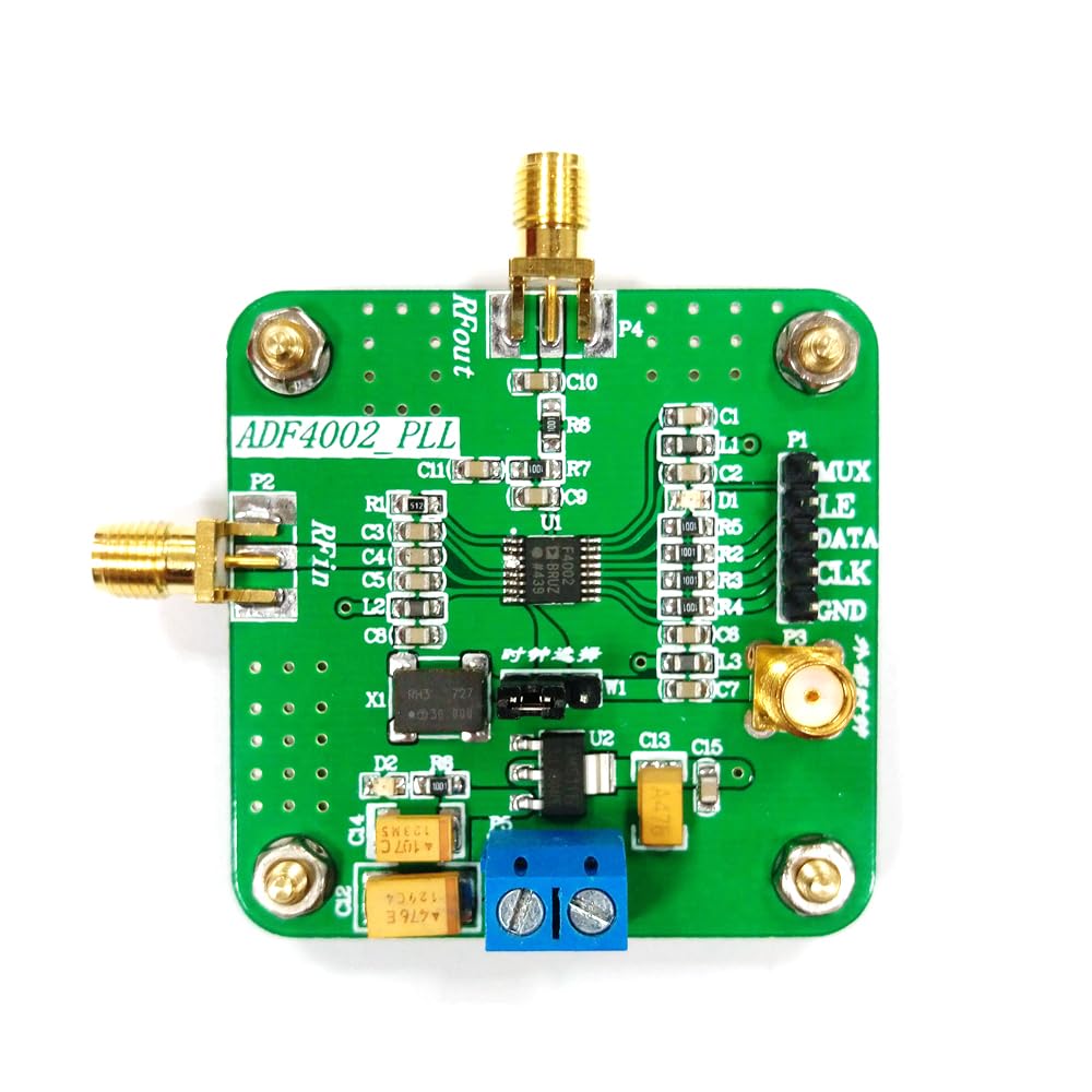
Figure 4.1: Labeled diagram of the ADF4002 module. This image highlights the key connection points including the RF input (RFin), RF output (RFout), power supply terminals, digital control interface (MUX, LE, DATA, CLK, GND), external clock access, and the loop filter area. It also indicates the 30MHz crystal oscillator and the output to VCO.
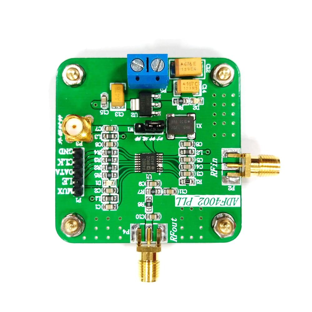
Figure 4.2: Top-down view of the ADF4002 High-frequency Analog Digital Phase Detector Phase-locked Loop Module. This image provides a clear view of the module's layout, including the SMA connectors for RF input and output, the screw terminal for power, and the header pins for digital control.
5. Operating Instructions
The ADF4002 module operates as a core component in a phase-locked loop system. Its primary function is to compare the phase and frequency of two input signals and generate an error voltage that drives a VCO to achieve phase lock.
Basic Operation:
- Power On: Ensure all connections are secure and apply power within the specified voltage range (5-9V DC).
- Programming: Use the 3-wire serial interface to program the internal registers of the ADF4002. This includes setting the R and N counters, charge pump current, and operating modes. Detailed programming information can be found in the official Analog Devices ADF4002 datasheet.
- Signal Input: Apply the reference frequency to the RFin port and the feedback signal from the VCO to the RFout port (which acts as the input to the phase detector from the VCO in a closed loop).
- Lock Detection: Monitor the analog and digital lock detection outputs to confirm that the PLL has achieved a locked state. A locked state indicates that the output frequency of the VCO is a precise multiple of the reference frequency, and their phases are aligned.
- Charge Pump Control: The programmable charge pump current allows fine-tuning of the loop filter characteristics, influencing the PLL's lock time, phase noise, and spurious performance.
For advanced applications and detailed register configurations, it is highly recommended to consult the official Analog Devices ADF4002 datasheet, which provides comprehensive technical specifications and programming guides.
6. Maintenance
The ADF4002 module is designed for robust operation with minimal maintenance. Adhering to these guidelines will help ensure its longevity and reliable performance:
- Cleanliness: Keep the module clean and free from dust, dirt, and moisture. Use a soft, dry cloth for cleaning. Avoid using harsh chemicals or abrasive materials.
- Handling: Handle the module by its edges to avoid touching the electronic components. Static electricity can damage sensitive components, so use anti-static precautions when handling.
- Storage: Store the module in a dry, cool environment, away from direct sunlight and extreme temperatures. If storing for extended periods, use anti-static bags.
- Connections: Periodically check all connections (power, RF, digital) to ensure they are secure and free from corrosion. Loose connections can lead to intermittent operation or signal degradation.
- Ventilation: Ensure adequate airflow around the module if it is enclosed, especially during continuous operation, to prevent overheating.
7. Troubleshooting
If you encounter issues with your ADF4002 module, refer to the following troubleshooting guide:
| Problem | Possible Cause | Solution |
|---|---|---|
| No Power Indication | Incorrect power supply voltage or polarity; loose power connection. | Verify power supply voltage is within 5-9V and polarity is correct. Check power cable connections. |
| PLL Not Locking | Incorrect programming of R/N counters; improper loop filter design; insufficient input signal level; faulty VCO. | Review programming settings against ADF4002 datasheet. Check loop filter components. Ensure adequate RF input signal strength. Verify VCO functionality. |
| Unstable Output Frequency | Poor loop filter design; noisy power supply; external interference. | Optimize loop filter components. Use a regulated and filtered power supply. Shield the module from external RF interference. |
| Communication Errors (Serial Interface) | Incorrect wiring of MUX, LE, DATA, CLK lines; wrong communication protocol. | Double-check wiring. Ensure your microcontroller/controller is using the correct 3-wire serial protocol as specified in the ADF4002 datasheet. |
If the problem persists after attempting these solutions, please contact customer support for further assistance.
8. Warranty Information
This Q-BAIHE ADF4002 module comes with a standard manufacturer's warranty against defects in materials and workmanship. The warranty period typically begins from the date of purchase. Please retain your proof of purchase for warranty claims.
The warranty does not cover damage caused by:
- Improper installation or use.
- Accidental damage, misuse, abuse, or neglect.
- Unauthorized repairs or modifications.
- Operating outside the specified voltage or environmental conditions.
For specific warranty terms and conditions, refer to the documentation provided with your purchase or contact Q-BAIHE customer support.
9. Customer Support
For technical assistance, product inquiries, or warranty claims, please contact Q-BAIHE customer support.
- Online Support: Visit the official Q-BAIHE store on Amazon or their official website for FAQs and support resources.
- Email Support: Refer to your product packaging or purchase invoice for direct email contact information.
- Documentation: Always refer to the official Analog Devices ADF4002 datasheet for in-depth technical details and programming guides, as this manual provides a general overview.
When contacting support, please have your product model number (Q-BAIHE ADF4002) and purchase details ready.