Introduction
This manual provides essential information for the proper use, installation, and maintenance of the Generic 2512 0.005R 5mR R005 Chip Resistor Alloy. These components are designed for precise current sensing applications, offering low resistance and high power dissipation in a compact surface-mount package. Please read this manual thoroughly before using the product to ensure optimal performance and safety.
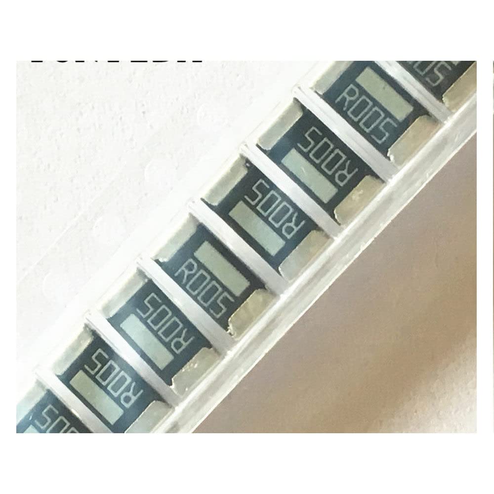
Image: A strip of Generic 2512 0.005R 5mR R005 Chip Resistors. Each resistor is clearly marked with "R005", indicating its resistance value. These components are typically supplied in tape-and-reel packaging for automated assembly processes.
Specifications
| Attribute | Value |
|---|---|
| Product Type | Chip Resistor Alloy |
| Quantity | 50 PCS |
| Package Size | 2512 |
| Resistance Value | 0.005 Ohm (5mR) |
| Marking | R005 |
| Power Rating | 2W |
| Tolerance | 1% |
| Manufacturer | Generic |
| ASIN | B0CN69MFF4 |
| First Available Date | November 13, 2023 |
Setup and Installation
These chip resistors are surface-mount devices (SMD) and require specific handling and soldering techniques for proper installation.
- Preparation: Ensure the PCB (Printed Circuit Board) pads are clean and free from contaminants. Use appropriate solder paste for reflow soldering or fine-tip soldering iron for manual placement.
- Placement: Carefully place the resistor onto the designated pads on the PCB. Automated pick-and-place machines are recommended for high-volume production. For manual placement, use fine tweezers.
- Soldering:
- Reflow Soldering: Follow the recommended reflow profile for your solder paste. Ensure proper temperature ramp-up, soak, reflow, and cooling stages to prevent thermal stress and ensure good solder joints.
- Manual Soldering: Use a temperature-controlled soldering iron (typically 300-350°C) with a small tip. Apply a small amount of solder to one pad, place the resistor, then solder the other pad. Minimize heating time to prevent component damage.
- Inspection: After soldering, visually inspect the solder joints for proper wetting, absence of bridges, and correct alignment.
Note: Proper ESD (Electrostatic Discharge) precautions should be observed during handling and installation to prevent damage to sensitive electronic components.
Operating Principles
The 2512 0.005R 5mR R005 chip resistor is primarily used as a current sense resistor. Its low resistance value allows it to be placed in series with a load to measure current flow with minimal voltage drop and power loss. The voltage drop across the resistor (V = I * R) can then be measured by an analog-to-digital converter (ADC) or an operational amplifier circuit to determine the current (I = V / R).
- Current Sensing: Connect the resistor in series with the circuit where current measurement is required.
- Voltage Measurement: Measure the voltage across the resistor using a high-impedance voltmeter or an appropriate differential amplifier circuit.
- Power Dissipation: Ensure that the power dissipated by the resistor (P = I² * R) does not exceed its 2W rating. Exceeding this rating can lead to overheating and component failure.
Maintenance and Storage
These resistors are passive components and generally require no active maintenance once installed. However, proper storage and handling are crucial before installation.
- Storage: Store resistors in their original packaging in a dry, cool environment, away from direct sunlight and extreme temperatures. Humidity control is recommended to prevent oxidation of solderable terminals.
- Handling: Handle components with clean, dry hands or appropriate tools (e.g., tweezers). Avoid touching the terminals directly to prevent contamination.
- Cleaning: If necessary, clean the PCB assembly after soldering using standard electronic cleaning agents. Avoid harsh chemicals that may damage the component or solder joints.
Troubleshooting
Most issues related to chip resistors stem from improper installation or exceeding operational limits.
- No Current Reading / Open Circuit:
- Check solder joints for cold joints or insufficient solder.
- Verify continuity across the resistor using a multimeter.
- Ensure the resistor is correctly placed on the pads.
- Incorrect Current Reading:
- Confirm the correct resistor value (R005) is installed.
- Check for parallel resistance paths or short circuits on the PCB.
- Verify the accuracy of the voltage measurement circuit.
- Resistor Overheating / Damage:
- Ensure the current flowing through the resistor does not cause power dissipation to exceed 2W.
- Check for proper heat dissipation from the PCB pads.
- Verify the resistor is not subjected to excessive voltage spikes.
If issues persist, consult a qualified electronics technician or refer to the circuit design documentation.
Warranty and Support
As a generic electronic component, specific warranty information may vary depending on the distributor or seller from whom the product was purchased. Please refer to your purchase documentation for details regarding returns, refunds, or replacements.
For technical support or inquiries regarding the specifications and application of these chip resistors, it is recommended to consult general electronics engineering resources or contact your component supplier.
For purchases made via Amazon, please refer to the Amazon Return Policy for eligible returns and support options.


