1. Introduction
This manual provides comprehensive instructions for the safe and effective operation, setup, maintenance, and troubleshooting of your LVCHEN Orion Pulse Arc Welder. This device is designed for precision spot welding applications, primarily for permanent jewelry, dental materials, and eyeglass frames.
Please read this manual thoroughly before operating the welder to ensure proper use and to prevent damage or injury.

Figure 1.1: LVCHEN Orion Pulse Arc Welder and its primary application in permanent jewelry.
2. Safety Instructions
WARNING: Improper use of welding equipment can cause serious injury or death. Always follow safety precautions.
- Always wear appropriate personal protective equipment (PPE), including welding goggles or safety glasses, to protect your eyes from arc flash.
- Ensure the work area is well-ventilated to avoid inhaling welding fumes.
- Do not touch live electrical parts. Ensure the power is off and unplugged before performing any maintenance or adjustments.
- Keep flammable materials away from the welding area.
- This product is intended for welding jewelry clasps to join jewelry together. It cannot be used for welding metal bars or drilling holes.
- The welding diameter range is 0.8-3mm. Welding outside this range may not yield good results or may prevent the unit from working correctly.

Figure 2.1: Important limitations and correct welding caliber (0.8-3mm) for the Orion Pulse Arc Welder. Do not use for welding metal bars, drilling, or complex jewelry structures.
3. Package Contents
Verify that all items listed below are included in your package. If any items are missing or damaged, please contact customer support.

Figure 3.1: Complete accessory list for the Pulse Arc Welder.
- Pulse Arc Welder Unit
- Welding Handle with Stand
- Power Cord
- Pneumatic Pressure Gauge (for optional argon connection)
- Argon Gas Tube
- Grinder (for welding needles)
- Loop Clamp
- Welding Tweezers
- Curved Mouth Pointed Tweezers (175mm)
- Red Handle Cutting Pliers
- Red Handle Pointed Nose Pliers
- Hexagonal Wrench
- Goggles
- 10 Tungsten Welding Needles
- 4 Copper Collets (1.0*2pcs, 0.6*2pcs)
4. Product Components and Connections
Familiarize yourself with the main components and connection points of the welder unit.

Figure 4.1: Front panel controls and rear connections of the Pulse Arc Welder.
Front Panel:
- Wait Indicator: Illuminates when the unit is charging.
- Ready Indicator: Illuminates when the unit is ready for welding.
- Welding Power Adjustment: Up/Down buttons to adjust welding power (%). Display shows power in %.
- Welding Time Adjustment: Up/Down buttons to adjust welding time (ms). Display shows time in ms.
- Material Selection Buttons:
- Au (Gold)
- Co-Cr (Cobalt-chromium alloy)
- Hybrid (Mixed)
- Titan (Pure Titanium)
- Ortho (Orthodontic)
- Program Button: For advanced settings or custom programs.
- Select Button: To confirm selections or adjust bleed time.
Rear Panel:
- Power Switch: On/Off toggle.
- Power Connector: For connecting the power cord. Includes two fuses (one spare).
- 6mm Argon Gas Interface: For optional argon gas connection.
- Negative Circuit Interface: Connects to the workpiece clamp.
- Welding Handle Interface: Connects the welding handle.
5. Setup and Installation
5.1. Initial Setup
- Place the welder unit on a stable, flat surface.
- Connect the welding handle to the "Welding Handle Interface" on the rear panel. Place the handle in its stand.
- Connect the negative circuit clamp to the "Negative Circuit Interface" on the rear panel.
- Ensure the power switch is in the OFF position. Connect the power cord to the "Power Connector" and then to a standard 110V AC outlet.
5.2. Welding Needle Installation and Preparation
The tungsten welding needles require preparation before use.

Figure 5.1: Installation process for the tungsten electrode into the welding handle.
- Unscrew the welding handle cover.
- Select a copper collet appropriate for the chosen tungsten needle diameter. Insert the copper collet into the welding handle.
- Use the provided grinder to sharpen the end of a tungsten welding needle into a sharp point. This ensures a precise arc.
- Insert the sharpened tungsten needle into the copper collet. Adjust its position so that 10-15mm of the needle extends beyond the handle cover when reassembled.
- Screw the welding handle cover back on, securing the needle.
5.3. Optional Argon Gas Connection
Connecting an argon gas bottle (not included) can improve welding quality, especially for certain materials or finer work. Ensure gas supply pressure is at least 0.1Mpa.
- Connect the pneumatic pressure gauge to your argon gas bottle.
- Connect the argon gas tube from the pressure gauge to the "6mm Argon Gas Interface" on the rear of the welder.
- Ensure all connections are secure to prevent gas leaks.
6. Operation
6.1. Power On and Readiness Check
- Turn on the power switch on the rear panel.
- The "Wait" indicator will illuminate as the unit charges. Once charged, the "Ready" indicator will light up, indicating the welder is ready for use.
6.2. Setting Welding Parameters
Adjust welding power and time based on the material and thickness of the workpiece. Refer to the diagram below for control panel details.
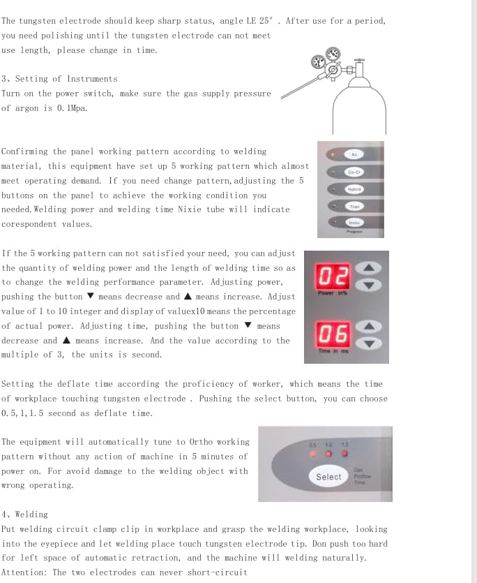
Figure 6.1: Adjusting welding power and time settings.
- Material Selection: Press the corresponding button (Au, Co-Cr, Hybrid, Titan, Ortho) for the material you are welding.
- Welding Power: Use the Up/Down buttons next to "Power in %" to adjust the welding power. Adjust from 1 to 10, where 10 represents 100% power.
- Welding Time: Use the Up/Down buttons next to "Time in ms" to adjust the welding time. Adjust in multiples of 3.
- Deflate Time (Argon Bleed Time): If using argon, press the "Select" button to adjust the gas bleed time (e.g., 0.5, 1, 1.5 seconds). This controls how long argon flows after the weld.
Note: The equipment will automatically tune to Ortho welding pattern without any action after 5 minutes of power on. For welding other objects, adjust settings accordingly.
6.3. Welding Process (Spot Welding)

Figure 6.2: Performing a spot weld.
- Secure the workpiece using the loop clamp, ensuring good electrical contact with the negative circuit.
- Position the workpiece close to the welding needle. The workpiece should be stable and not shaking, as this can affect welding induction.
- Gently touch the workpiece to the welding needle. The welder will automatically initiate the spot weld and retract the rod.
- After welding, inspect the joint. If necessary, adjust welding power and time for optimal results.
Attention: The two electrodes (welding needle and workpiece clamp) should never short-circuit.
6.4. Applications
Beyond permanent jewelry, this welder is versatile for other precision welding tasks.

Figure 6.3: Versatile applications including jewelry repair, eyeglass repair, and orthodontics.
- Jewelry Repair: Ideal for delicate repairs and joining small components.
- Eyeglass Repair: Suitable for welding metal eyeglass frames.
- Orthodontics: Can be used for welding dental materials.
7. Maintenance
7.1. Welding Needle Maintenance
- The tungsten electrode should always have a sharp point (angle approximately 25°).
- If there is any debris stuck on the surface of the soldering pin after use, or if the point becomes dull, use the provided grinder to re-sharpen it. A dull needle can affect weld quality.
- Replace the welding needle if it becomes too short or damaged to be effectively sharpened.
7.2. General Cleaning
- Ensure the unit is unplugged and cooled down before cleaning.
- Wipe the exterior of the welder with a soft, dry cloth. Do not use abrasive cleaners or solvents.
- Keep the ventilation openings clear of dust and debris.
8. Troubleshooting
| Problem | Possible Cause | Solution |
|---|---|---|
| Welder does not power on. | No power supply; Power switch off; Blown fuse. | Check power cord connection and outlet; Ensure power switch is ON; Check and replace fuses if necessary (spare fuse included). |
| "Wait" light stays on, "Ready" light does not illuminate. | Unit not fully charged; Internal issue. | Allow more time for charging; If problem persists, contact customer support. |
| Poor weld quality or no weld. | Incorrect power/time settings; Dull or dirty welding needle; Poor workpiece contact; Workpiece diameter outside range. | Adjust welding power and time; Re-sharpen or clean welding needle; Ensure workpiece is securely clamped and making good contact; Verify workpiece diameter is between 0.8-3mm. |
| Welding induction issues (welder not firing). | Workpiece shaking; Workpiece not close enough to needle. | Ensure workpiece is stable and held firmly; Bring workpiece closer to the welding needle. |
| Problems installing argon meter. | Incorrect connection or incompatible parts. | Contact customer support for specific guidance. |
9. Specifications
Technical specifications for the LVCHEN Orion Pulse Arc Welder.

Figure 9.1: Detailed product parameters.
| Parameter | Value |
|---|---|
| Input Voltage/Frequency | 110V/60Hz |
| Input Power | 100W |
| Fuse | 250V/2.0A |
| Protection Grade | IP21 |
| Gas Supply Pressure | ≥0.1Mpa |
| Welding Voltage | 40V |
| Welding Current | 50A-600A |
| Welding Time | 3ms-30ms |
| Maximum Welding Frequency | 1Hz |
| Maximum Argon Consumption | 5L/min |
| Item Weight | 16.02 pounds |
| Package Dimensions | 14 x 12 x 11 inches |
| Model Number | cx-dhj-fba2 |
10. Warranty and Support
For warranty information, technical support, or assistance with any issues not covered in this manual, please contact LVCHEN customer service through the retailer where you purchased the product or visit the official LVCHEN store on Amazon.
LVCHEN Store Link: https://www.amazon.com/stores/LVCHEN/page/3742CFF6-A63E-4910-9AFC-E9F7F32C9C19


