DeWin KMCBLFKLL-GS109479-01
DEWIN 220V 0.75kW VFD Frequency Converter User Manual
Model: KMCBLFKLL-GS109479-01
1. Introduction
This manual provides detailed instructions for the installation, operation, and maintenance of the DEWIN 220V 0.75kW Variable Frequency Drive (VFD). This device is designed to control the speed of three-phase motors using a single-phase 220V input. Please read this manual thoroughly before using the product to ensure safe and efficient operation.
2. Safety Instructions
WARNING: Risk of electrical shock. Wait 10 minutes after removing power before servicing.
Always adhere to the following safety precautions to prevent injury or damage to the equipment:
- Ensure the power supply is disconnected before any installation, wiring, or maintenance work.
- Only qualified personnel should perform installation and wiring.
- Verify that the input voltage matches the specifications of the VFD.
- Properly ground the unit to prevent electrical hazards.
- Do not connect the power supply to the output terminals (U, V, W).
- Avoid operating the VFD in environments with excessive dust, moisture, or corrosive gases.
- Do not touch internal components immediately after power-off, as residual voltage may be present.

Image: The DEWIN VFD unit, showing the front panel and a warning label indicating electrical shock risk and the need to wait 10 minutes after power removal before servicing.
3. Product Overview
3.1 Key Features
- Single-phase 220V input, three-phase 220V output.
- Motor protection features.
- Energy-saving capabilities.
- Adjustable output frequency (0-999Hz).
- Strong security and stable operation.
- Removable control panel for flexible installation.
- Equipped with a radiator for efficient heat dissipation.

Image: The DEWIN VFD highlighting its core benefits: motor protection, energy saving, frequency control, and strong security.
3.2 Components and Control Panel
The VFD consists of the main unit and a detachable control panel. The control panel allows for easy operation and parameter setting.
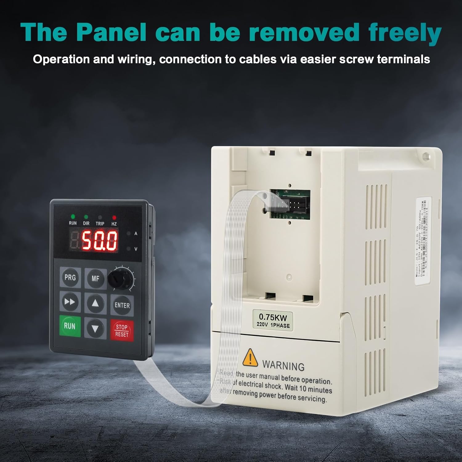
Image: The DEWIN VFD demonstrating its removable control panel, which can be connected via a cable for remote operation and easier wiring access.

Image: A close-up of the VFD's operation interface, clearly labeling the status indication lights (RUN, DIR, TRIP, HZ), digital display, electric current (A) and voltage (V) indicators, Multifunction key (MF), Menu key (PRG), Shift key, up and down selection keys, Run key, Enter key, Stop button, and Reset button, along with the Speed knob.
4. Specifications
| Parameter | Value |
|---|---|
| Model | JLS-E-2S-0.75G |
| Material | Process flame retardant ABS plastic |
| Color | White |
| Rated Input Voltage | Single Phase 220V |
| Rated Output Voltage | Three-phase 220V |
| Rated Power | 0.75KW |
| Output Current | 5A |
| Factory Frequency | 50Hz |
| Output Frequency Range | 0~999Hz |
| Installation Method | Wall-mounted, cabinet |
| Nature of DC Power Supply | Voltage Type |
| Control Mode | V/F closed loop |
| Output Voltage Regulation Method | PAM control |
| Dimensions (W x H x D) | 85mm x 140mm x 115mm |
| Weight | 1.12 Kilograms |
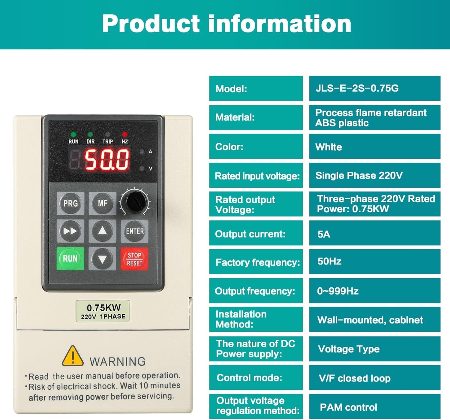
Image: A table detailing the product specifications including model, material, color, input/output voltages, power, current, frequency range, installation method, and control modes.

Image: Diagram showing the physical dimensions of the DEWIN VFD, with measurements of 85mm width, 140mm height, and 115mm depth.
5. Setup and Installation
5.1 Mounting
The VFD can be wall-mounted or installed within a cabinet. Ensure adequate ventilation around the unit for proper heat dissipation.

Image: The DEWIN VFD showcasing its integrated radiator and cooling fan, with blue arrows illustrating the airflow path for effective heat dissipation, ensuring stable long-term operation.
5.2 Wiring
Follow the wiring diagram carefully. Incorrect wiring can damage the unit or connected equipment.
- L1, L2: Connect to the single-phase 220V power supply.
- P, PB: These terminals are typically for braking resistors if required (refer to advanced manual for details).
- U, V, W: Connect to the three-phase motor terminals.
- Ground: Ensure a proper ground connection for safety.

Image: A clear wiring diagram for the 220V inverter, illustrating the connections for the single-phase 220V power supply (L1, L2), the ground wire, and the three-phase motor (U, V, W).
6. Operating Instructions
6.1 Basic Operation
- Power On: After completing all wiring, apply power to the VFD. The display will light up.
- Set Frequency/Speed: Use the Speed knob on the control panel to adjust the desired output frequency, which directly controls the motor speed.
- Start Motor: Press the RUN button to start the motor. The "RUN" indicator light will illuminate.
- Stop Motor: Press the STOP/RESET button to stop the motor. The "RUN" indicator light will turn off.
- Reset Faults: If a fault occurs (e.g., "TRIP" indicator lights up), address the cause, then press the STOP/RESET button to clear the fault and reset the VFD.
6.2 Advanced Parameter Settings
The VFD offers a wide range of programmable parameters for fine-tuning performance. Refer to the detailed parameter list (often provided in a separate, more comprehensive manual) for specific settings related to acceleration/deceleration times, motor parameters, control modes, etc.
- Use the PRG (Program/Menu) button to enter the parameter setting mode.
- Use the Up/Down arrows to navigate through parameters.
- Use the ENTER button to select a parameter and confirm changes.
- Use the Shift key (left/right arrows) to move the cursor when editing numerical values.
- The MF (Multifunction) key may be used for quick access to frequently used functions or to switch display modes.
7. Maintenance
Regular maintenance ensures the longevity and reliable operation of your VFD.
- Cleaning: Periodically clean the VFD's exterior and ventilation openings to prevent dust accumulation, which can hinder heat dissipation. Use a soft, dry cloth. Do not use liquid cleaners.
- Inspection: Regularly inspect wiring connections for looseness or signs of damage. Check for any unusual noises or smells during operation.
- Environment: Ensure the operating environment remains within specified temperature and humidity ranges.
- Capacitor Discharge: Remember the 10-minute waiting period after power-off before touching internal components due to residual capacitor charge.
8. Troubleshooting
This section provides solutions for common issues. For complex problems, contact customer support.
| Problem | Possible Cause | Solution |
|---|---|---|
| VFD does not power on | No input power; incorrect wiring | Check power supply and input wiring (L1, L2). |
| Motor does not run | Incorrect motor wiring (U, V, W); VFD in fault state; parameters not set correctly | Verify motor connections; check for fault codes on display and reset; review basic operating parameters. |
| "TRIP" indicator is on | Overcurrent, overvoltage, undervoltage, overload, overheating | Identify the specific fault code (if displayed); check motor load, input voltage, and VFD temperature. Press STOP/RESET to clear. |
| Motor speed is unstable | Improper V/F curve setting; motor parameters incorrect; external interference | Adjust V/F curve parameters; ensure motor data is correctly entered; check for electromagnetic interference. |
9. Warranty and Support
DEWIN products are manufactured to high quality standards. For warranty information, technical support, or service inquiries, please refer to the warranty card included with your product or contact your local distributor. You may also visit the official DEWIN website for further assistance.
For general inquiries, you can visit the DEWIN Brand Store on Amazon.
Ask a question about this manual
Ask about setup, troubleshooting, compatibility, parts, safety, or missing instructions. Manuals+ will review the question and use this page’s manual context to help answer it.