Hosyond B0CMD7Y55M
Instruction Manual
Hosyond 3.5 inch 320x480 IPS Capacitive Touch Screen LCD Module
1. Introduction
This instruction manual provides detailed information for the setup, operation, and maintenance of your Hosyond 3.5 inch 320x480 IPS Capacitive Touch Screen LCD Module. Designed for seamless integration with Arduino R3/Mega2560 and other MCUs, this module offers a vibrant display and responsive touch interface for your electronic projects. Please read this manual thoroughly before use to ensure proper functionality and longevity of the product.
2. Product Overview
The Hosyond 3.5-inch LCD module features an IPS capacitive touch screen, offering excellent visual performance and responsive interaction. It is designed for various embedded applications, particularly with Arduino and other microcontrollers.
2.1 Key Features
- High-Quality Display: 3.5-inch IPS full-viewing panel with 320x480 resolution, 300cd/m2 brightness, and 16.7M RGB colors for superior display effects.
- Capacitive Touch: Newly upgraded capacitive touch panel provides sensitive and precise touch response.
- Wide Compatibility: On-board level conversion circuit compatible with 5V and 3.3V MCUs.
- Efficient Interface: Utilizes 4-wire SPI serial bus to minimize I/O pin usage.
- Flexible Connectivity: Supports 2.54mm pin header interface and FPC extension interface.
- Storage Expansion: Includes a micro TF card slot for easy storage expansion of fonts and images.
- Extensive Support: Rich sample learning programs and underlying driver technical support for ESP32, STM32, Arduino R3 & Mega2560, C51, and CH32.
2.2 Product Visuals

Figure 1: Hosyond 3.5 inch IPS Capacitive Touch Screen LCD Module.

Figure 2: The capacitive touch screen allows direct hand touch, eliminating the need for a stylus.

Figure 3: Comparison highlighting the advantages of IPS technology over traditional TFT, including richer colors, higher brightness, and excellent viewing angles.
3. Specifications
3.1 Display and Touch Parameters
| Parameter | Value | Parameter | Value |
|---|---|---|---|
| Screen Size | 3.5 inch | Touch Active Area | 3.5 inch |
| Screen Type | IPS | Touch Screen Type | Capacitive Touch Screen |
| Resolution | 320xRGBx480 (pixels) | Touch Screen Resolution | 320x480 (pixels) |
| Active Area (AA area) | 48.96(W)x73.44(H)(mm) | Driver IC | FT6336U |
| Number of Colors (Max) | 16.7M | Touch Screen Visual Area | 49.56(w)x74.04(H)(mm) |
| Driver IC | ST7796U | Communication Interface | IIC |
| Display Interface | 4-Line SPI | Operation Temperature | -20~70(℃) |
| Pixel Size | 0.153(H)x0.153(mm) | Storage Temperature | -30~80(℃) |
| View Angle | ALL 0’CLOCK | ||
| Brightness (TYP) | 300(cd/m2) | ||
| Backlight Type | White LED*6 | ||
| Operation Temperature | -10~50(℃) | ||
| Storage Temperature | -20~60(℃) |
3.2 Electrical Parameters
- Working Voltage: 5.0 V
- Backlight Current: 95 mA
- Power: 0.5 W
3.3 Physical Parameters
- Interface: 4P 2.54mm spacing Header and 0.5mm spacing FPC seat
- Size (including Pin Header): 55.5(W)x98.0(H)x12.98(D)(mm)
- Weight (including package): 82g
4. Package Contents
The product package includes the following items:
- 1 x 3.5 inch touch screen module
- 1 x FPC cable
- 1 x Plastic protective box
5. Setup and Connection
This section details the physical connections and initial setup for your LCD module.
5.1 Interface Function Description

Figure 4: Diagram illustrating the various interfaces and their functions on the module.
| No. | Interface | Function Description |
|---|---|---|
| ⒈ | 14 Pin Header | 2.54mm spacing row pins, module signal input pins. |
| ⒉ | Micro SD Slot | Insert a Micro SD card to expand storage space for fonts, images, etc. |
| ⒊ | 14P FPC | 0.5mm FPC terminal, used for module signal input with the same function as ⒈. |
5.2 General Connection Guidelines
The module is designed for compatibility with 5V and 3.3V MCUs. It uses a 4-wire SPI interface for display data and an IIC interface for the capacitive touch screen. Ensure all necessary pins are connected to your development board.
- Power Supply: Connect the module to a stable 5.0V power source.
- SPI Connections: Connect the SPI pins (MOSI, MISO, SCLK, CS, DC) to the corresponding pins on your MCU.
- Touch (IIC) Connections: Connect the IIC pins (SDA, SCL) to your MCU. For Arduino Mega2560, CTP_SCL typically connects to pin 21 and CTP_SDA to pin 20.
- Reset Pin (RST): The module's RST pin must be connected to the controller's RST pin to prevent a white screen issue.
- LED/Backlight Pin: The backlight is always on, so connecting the LED pin is generally not necessary unless specific backlight control is desired.
- Micro SD Card: The Micro SD card slot functions by simply connecting the SD pin.

Figure 5: Rear view of the module, highlighting the pin headers and Micro SD card slot.
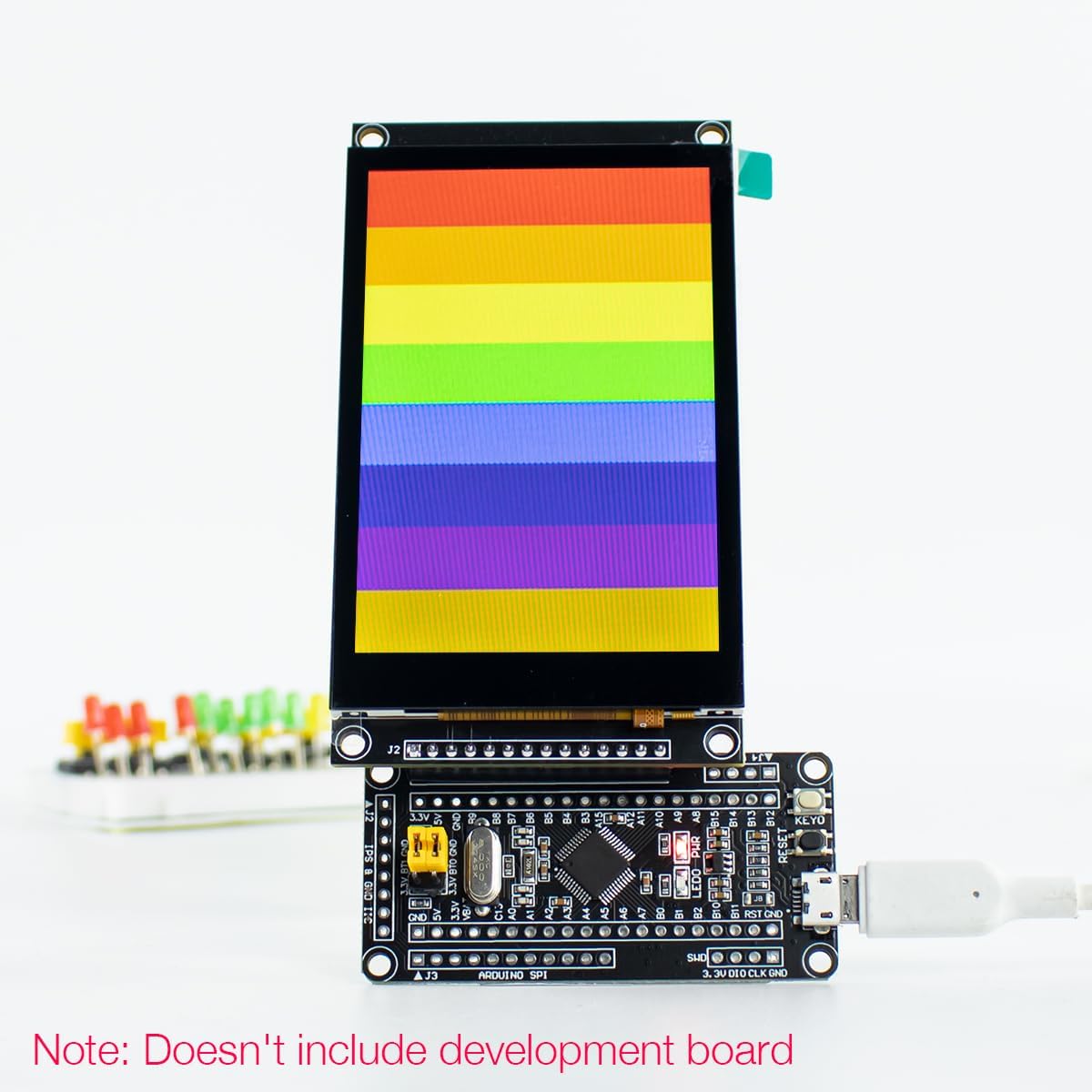
Figure 6: Example of the LCD module connected to a development board (development board not included).
5.3 Setup Demonstration Video
Video 1: A demonstration of the IPS Capacitive Touch Screen for Arduino, showcasing its display capabilities and touch functionality. This video provides a visual guide to the module's operation.
6. Operating Instructions
Once the module is correctly connected and powered, you can begin programming your MCU to interact with the display and touch screen.
- Software Libraries: Utilize provided sample learning programs and underlying driver technical support. Popular libraries like TFT_eSPI for display control and Arduino-FT6336U for touch screen interaction are recommended.
- Display Control: Use the SPI interface to send display commands and pixel data. Refer to the ST7796U driver documentation for specific commands.
- Touch Input: The capacitive touch screen is highly responsive. Use the IIC interface to read touch coordinates from the FT6336U driver IC.
- Micro SD Card Usage: For expanding storage for graphics or data, insert a formatted Micro SD card into the dedicated slot. Ensure your code includes SD card library support to read/write data.
7. Maintenance
To ensure the longevity and optimal performance of your LCD module, follow these maintenance guidelines:
- Cleaning: Gently wipe the screen surface with a soft, lint-free cloth. For stubborn smudges, slightly dampen the cloth with distilled water or a screen-safe cleaner. Avoid abrasive materials or harsh chemicals.
- Handling: Avoid applying excessive pressure to the screen or bending the module. Handle by the edges to prevent damage to components.
- Storage: Store the module in a dry, dust-free environment, away from direct sunlight and extreme temperatures. The plastic protective box provided can be used for safe storage.
- Power: Always ensure a stable power supply within the specified voltage range (5.0V). Unstable power can lead to erratic behavior or damage.
8. Troubleshooting
This section addresses common issues you might encounter and provides potential solutions.
| Problem | Solution |
|---|---|
| Screen is white or blank. |
|
| Touch screen is unresponsive or erratic. |
|
| Display content is not full screen or incorrect resolution. |
|
| Micro SD card not detected. |
|
9. Warranty Information
Specific warranty details for this product are not provided in the available information. Please refer to the seller's or manufacturer's website for any applicable warranty policies or contact their customer support directly for inquiries.
10. Support
Hosyond is committed to providing rich usage information and reliable service to make your experience more convenient. For further technical support, documentation, or sample programs, please visit the official Hosyond store or contact their customer service.