1. Product Overview
The GOOZEEZOO GPSDO NEO-6M is an upgraded Global Positioning System Disciplined Oscillator designed for high accuracy and stable frequency output. It utilizes a GPS 1PPS signal to precisely control a temperature-compensated crystal oscillator, providing a highly accurate 10.000000.000MHz square wave output.

Image 1.1: The GOOZEEZOO GPSDO NEO-6M Disciplined Oscillator, showcasing its display and control knob.
Key Features:
- Enhanced Accuracy: Offers higher accuracy and lower temperature drift compared to standard timebases.
- Precise Control: Utilizes GPS 1PPS signal and a 16-bit PWM signal for fine-tuning the temperature-compensated crystal's output frequency.
- High-Precision Output: Delivers a 10.000000.000MHz ±0.001Hz square wave.
- Compact and Portable: Designed for portability with dimensions of 5.9 x 3.5 x 1.5 inches.
- Versatile Application: Suitable for high-end audio decoders, frequency meters, signal generators, and other devices requiring an external 10MHz reference source.
2. Specifications
Detailed technical specifications for the GPS Disciplined Oscillator are provided below:
| Parameter | Value |
|---|---|
| Item Type | GPS Disciplined Oscillator |
| Material | Aluminum Alloy |
| Power Supply Voltage | DC12V ±2V (Note: Power supply not included) |
| Working Current | 650mA (Preheating), 350mA (Stabilized) |
| Output Frequency | 10.000000.000MHz ±0.001Hz |
| Output Waveform | Square Wave |
| Output Amplitude | -45dBm |
| Thermostatic Crystal | ISOTEMP OCXO 143-141 (Disassembled) |
| GPS Module | NEO 6M (or ATGM336H GPS/Beidou Dual-Mode) |
| Product Dimensions | 9.3 x 6.3 x 2 inches (approx. 150mm x 88mm x 38mm) |
| Item Weight | 1.11 pounds |
3. Setup Instructions
Follow these steps to set up your GPS Disciplined Oscillator:
- Power Supply Connection: Connect a DC12V ±2V power supply (not included) to the device's power input port. Ensure the power supply meets the specified voltage and current requirements (minimum 1A recommended).
- GPS Antenna Connection: Connect the provided GPS antenna to the 'GPS ANT' port on the rear panel. Place the antenna in a location with a clear view of the sky to ensure optimal satellite reception.
- Output Connection: Connect your frequency meter, signal generator, or other compatible device to the 'Output' port using an appropriate cable.
- Power On: Flip the 'POWER SW' switch to the ON position. The device display will illuminate.

Image 3.1: Rear panel connections including power input, GPS antenna port, and output port.
4. Operating Instructions
This section details the operation and initial calibration process for the GPSDO.
Initial Power-On and Satellite Lock:
- Upon powering on, the screen will display "10.00MHz GPSDO".
- If a GPS antenna is not installed or has no satellite lock, this message will persist.
- Once the GPS antenna is installed and satellites are locked, the screen will display the PPb correction value and the current PWM adjustment value, derived from comparing with the 1PPS signal.
Calibration Process:
The initial calibration takes approximately 30 minutes. This process ensures the oscillator is precisely disciplined by the GPS signal.
- Allow the device to operate until the PPb value stabilizes within 0.0 ±1. This indicates a stable GPS lock and initial frequency correction.
- Press the encoding switch (rotary knob) to enter the menu.
- Rotate the encoder to navigate and find the "PWMSET" option.
- Press the encoder switch again to save the current PWM value. This stores the optimal adjustment for the crystal.
- Rotate the encoder to find "EXIT!! OK".
- Press the encoder switch to exit the menu. The calibration is now complete.
After completing and saving the PWM values, the GPS antenna is not strictly necessary for subsequent uses, as the device will maintain its calibrated accuracy.

Image 4.1: Visual guide for the calibration process, showing display messages for startup, satellite lock, PWM setting, and exit.
Applications:
The GPSDO is suitable for various applications requiring a precise 10MHz reference signal.
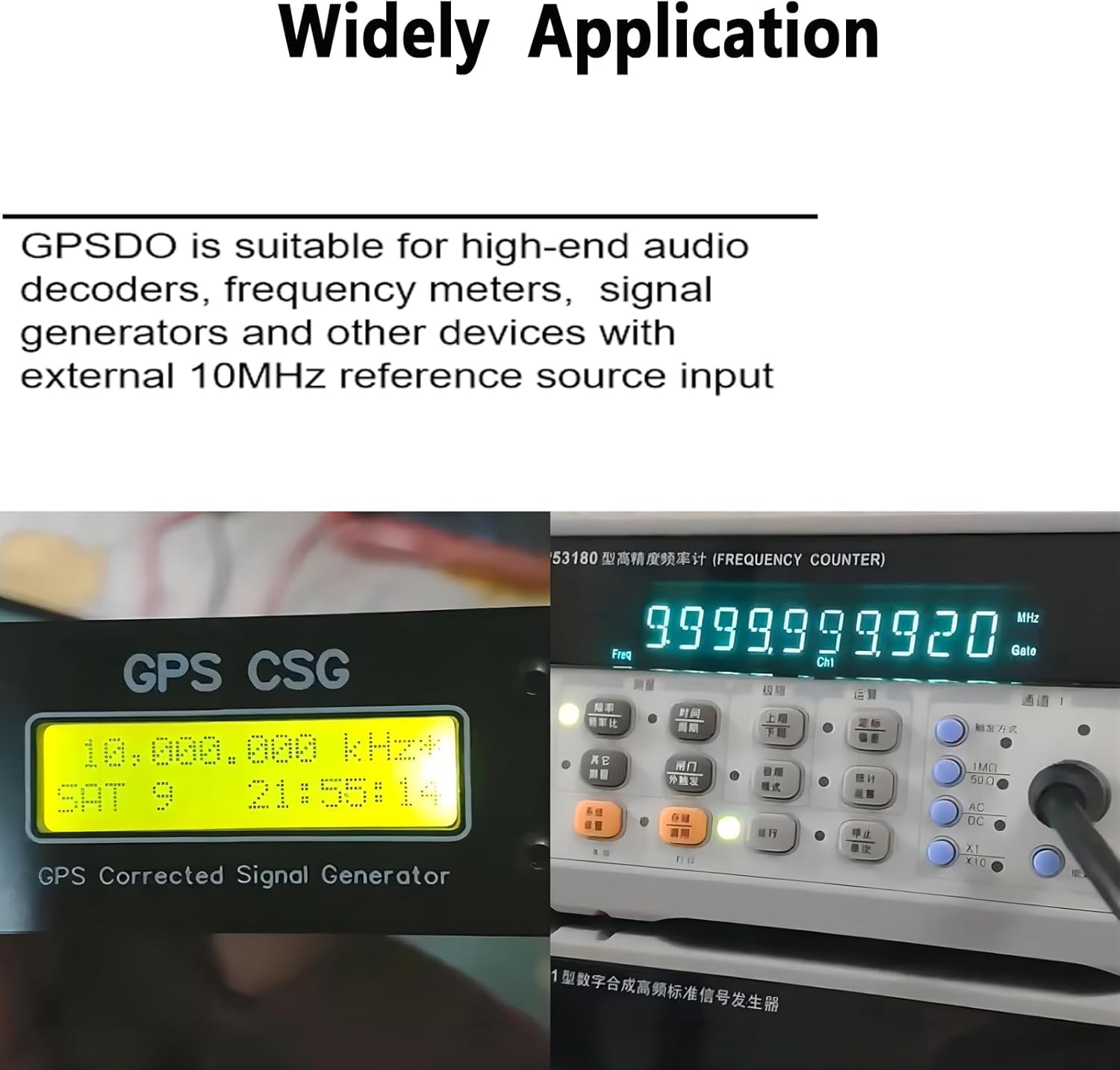
Image 4.2: The GPSDO connected to a frequency counter, demonstrating its application in providing a stable 10MHz reference.

Image 4.3: The GPSDO providing a stable 10MHz reference to a Hewlett Packard 5385A Frequency Counter.
5. Maintenance
To ensure the longevity and optimal performance of your GPS Disciplined Oscillator, follow these maintenance guidelines:
- Cleaning: Use a soft, dry cloth to clean the exterior of the device. Avoid using abrasive cleaners or solvents that could damage the finish or internal components.
- Environmental Conditions: Operate and store the device in a dry environment, away from extreme temperatures, direct sunlight, and high humidity.
- Cable Connections: Periodically check all cable connections (power, GPS antenna, output) to ensure they are secure and free from damage.
- Antenna Placement: Ensure the GPS antenna remains in a location with an unobstructed view of the sky for reliable satellite signal reception.
6. Troubleshooting
This section addresses common issues you might encounter with your GPS Disciplined Oscillator.
- Device Does Not Power On:
- Ensure the power supply is correctly connected and providing DC12V ±2V.
- Verify the power switch is in the ON position.
- Check the power adapter itself for functionality.
- Display Shows "10.00MHz GPSDO" Continuously:
- This indicates no GPS signal lock. Ensure the GPS antenna is securely connected to the 'GPS ANT' port.
- Relocate the GPS antenna to an outdoor area or a window with a clear, unobstructed view of the sky.
- Allow sufficient time (up to 30 minutes) for the device to acquire satellite signals.
- Inaccurate Frequency Output:
- Perform the calibration process as described in Section 4. Operating Instructions.
- Ensure the GPS antenna has a stable lock (PPb value near 0.0 ±1) during calibration.
- Note: Some users have reported a potential wiring issue from the main board to the controller on certain units, which may require advanced technical intervention. Consult the manufacturer if you suspect this issue.
- Power Supply Voltage Confusion:
- The device requires a DC12V ±2V power supply. While some components might operate at 9V internally, the external input should be 12V. Using an incorrect voltage may damage the device or lead to unstable operation.
7. Warranty and Support
GOOZEEZOO stands by the quality of its products.
Warranty Information:
This product typically comes with a 36-month warranty from the date of purchase, covering manufacturing defects and malfunctions under normal use. Please retain your proof of purchase for warranty claims. The warranty does not cover damage caused by misuse, unauthorized modifications, accidents, or improper power supply usage.
Customer Support:
For technical assistance, troubleshooting, or warranty inquiries, please contact GOOZEEZOO customer support. Refer to the product packaging or the official GOOZEEZOO website for the most current contact information.
Our company is dedicated to providing professional enthusiasts with superior listening experiences and endless enjoyment. We are ready to provide expert answers and top-notch service for your needs.