1. Introduction
This manual provides detailed instructions for the installation, operation, and maintenance of your Trisar KH140F Smart Battery Monitor. This device is designed to accurately measure and display various battery parameters, including voltage, current, power, capacity, and temperature, for a wide range of battery types such as lead-acid, lithium iron phosphate, and ternary lithium batteries. Please read this manual thoroughly before use to ensure proper functionality and safety.
2. Product Overview
The Trisar KH140F Smart Battery Monitor system consists of three main components: the display unit, the voltage/current measuring module, and the current sensor (shunt).

Figure 2.1: Trisar KH140F Smart Battery Monitor components including the display, measuring module, and current shunt.
2.1 Components
- Display Unit: Features a clear LCD screen for real-time data display and control buttons for navigation and settings.
- Voltage/Current Measuring Module: Processes voltage and current signals from the battery and shunt, and communicates with the display unit.
- Current Sensor (Shunt): A high-precision resistor used to measure the current flowing in and out of the battery.
- Connecting Cables: For power, communication, and temperature sensing.
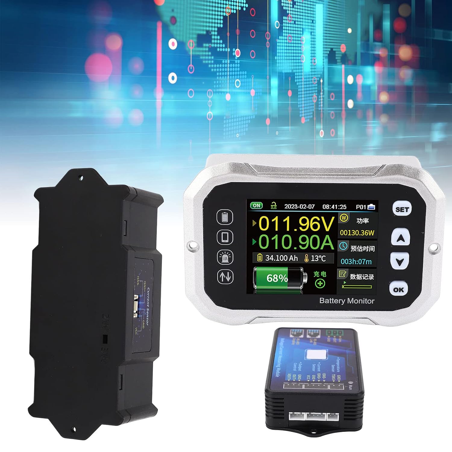
Figure 2.2: The display unit, voltage/current measuring module, and current shunt shown separately.
2.2 Key Features
- Wide voltage measurement range (0-120V).
- High current measurement capability (up to 400A with included shunt).
- Supports various battery types: lead-acid, lithium iron phosphate, ternary lithium.
- Real-time display of voltage, current, power, remaining capacity, and temperature.
- Estimated time remaining for charge/discharge.
- Data storage and historical record viewing.
3. Setup & Installation
3.1 Safety Precautions
- Ensure all power sources are disconnected before installation.
- Wear appropriate personal protective equipment (PPE), including safety glasses and gloves.
- Verify correct polarity for all connections to prevent damage to the device or battery.
- Do not exceed the specified voltage and current ratings of the device.
3.2 Wiring Diagram and Connections
Follow the wiring diagram carefully for proper installation. The current sensor (shunt) must be installed on the negative side of the battery circuit.
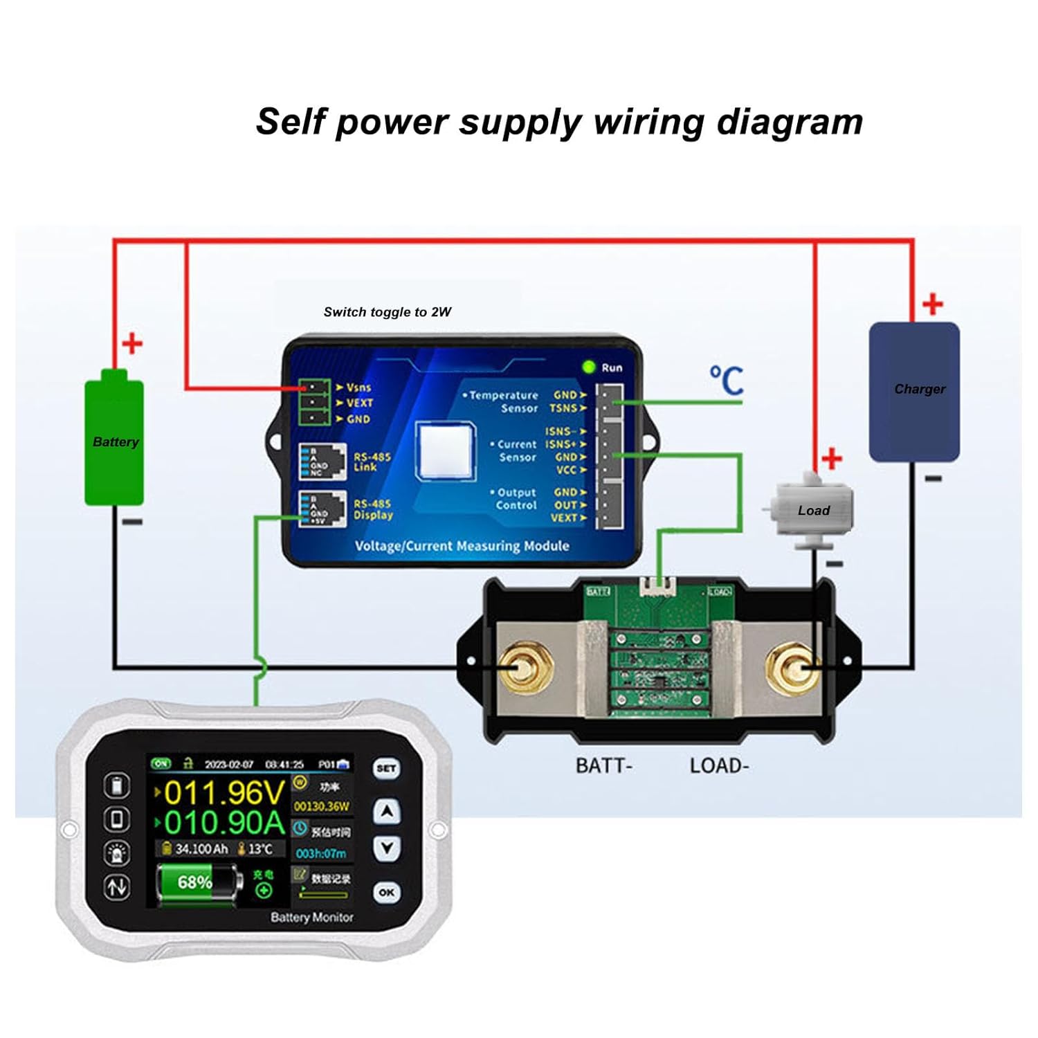
Figure 3.1: Self-power supply wiring diagram. This diagram illustrates how to connect the battery, load, charger, shunt, and measuring module to the display unit.
Connection Steps:
- Shunt Installation: Connect the negative terminal of your battery to the 'BATT-' terminal of the current shunt. Connect the 'LOAD-' terminal of the shunt to the negative terminal of your load and charger.
- Measuring Module to Shunt: Connect the small wires from the voltage/current measuring module to the shunt. Typically, ISNS+ and ISNS- connect to the corresponding terminals on the shunt.
- Measuring Module to Battery: Connect the VSNS wire from the measuring module to the positive terminal of the battery. Connect the VEXT wire to the positive terminal of the battery for self-powering the module, or to an external 10-120V power source if the battery voltage is outside the module's operating range. Connect the GND wire to the negative terminal of the battery or the 'BATT-' side of the shunt.
- Measuring Module to Display: Connect the RS-485 communication cable from the measuring module to the corresponding port on the back of the display unit.
- Temperature Sensor (Optional): If using a temperature sensor, connect it to the TSNS terminals on the measuring module.

Figure 3.2: Detailed view of the connection terminals on the Voltage/Current Measuring Module.

Figure 3.3: Back of the display unit, showing the communication port for connection to the measuring module.
4. Operating Instructions
4.1 Display Interface
The display unit provides a comprehensive overview of your battery's status. Key indicators include:
- Voltage (V): Current battery voltage.
- Current (A): Current flow (positive for charging, negative for discharging).
- Power (W): Instantaneous power consumption or generation.
- Capacity (Ah): Remaining battery capacity in Ampere-hours.
- Percentage (%): State of Charge (SOC).
- Temperature (°C): Battery temperature (if sensor is connected).
- Estimated Time: Remaining time for charge or discharge based on current usage.
4.2 Button Functions
- SET: Enters the settings menu or confirms a selection.
- UP (▲): Navigates up through menu options or increases a value.
- DOWN (▼): Navigates down through menu options or decreases a value.
- OK: Confirms a selection or exits a menu.
4.3 Basic Settings
To configure the monitor for your specific battery:
- Enter Settings: Press the SET button.
- Battery Type: Navigate to 'Battery Type' and select your battery chemistry (e.g., Lead-Acid, LiFePO4, Ternary Lithium) using the UP/DOWN buttons, then confirm with OK.
- Rated Capacity: Navigate to 'Rated Capacity' and input the total Ampere-hour (Ah) capacity of your battery bank. Confirm with OK.
- Voltage Limits: Set the over-voltage and under-voltage protection thresholds according to your battery manufacturer's recommendations.
- Current Calibration (if necessary): If current readings appear inaccurate, refer to the advanced settings for calibration procedures.
- Exit Settings: Press SET again or navigate to 'Exit' and confirm.
5. Maintenance
- Keep the display unit clean and free from dust and moisture. Use a soft, dry cloth for cleaning.
- Regularly check all wiring connections for tightness and corrosion. Loose connections can lead to inaccurate readings or device malfunction.
- Ensure adequate ventilation around the measuring module and shunt, especially during high current operation, to prevent overheating.
- Avoid exposing the device to extreme temperatures or direct sunlight for prolonged periods.
6. Troubleshooting
6.1 Common Issues and Solutions
- No Display/Power:
- Check all power connections to the measuring module and ensure the battery voltage is within the operating range.
- Verify the communication cable between the module and display is securely connected.
- Inaccurate Voltage Reading:
- Ensure the VSNS wire is connected directly to the battery positive terminal.
- Check for loose or corroded connections.
- Inaccurate Current Reading:
- Confirm the shunt is correctly installed on the negative side of the battery circuit, and all load/charger negative connections pass through it.
- Verify ISNS+ and ISNS- connections to the shunt are correct.
- Perform a current calibration if available in the settings menu.
- Incorrect Capacity/Percentage:
- Ensure the 'Rated Capacity' setting matches your battery's actual capacity.
- A full charge/discharge cycle may be required for the monitor to learn the battery's true capacity.
7. Specifications
| Parameter | Value |
|---|---|
| Brand | Trisar |
| Model Number | KH140F (Trisar7ey3wptcd0) |
| Measurement Type | Voltmeter, Ammeter, Wattmeter, Capacity Meter |
| Voltage Range | 0-120V |
| Current Range | Up to 400A (with included shunt) |
| Supported Battery Types | Lead-Acid, Lithium Iron Phosphate, Ternary Lithium |
| Power Source | Battery Powered (self-powered from 10-120V) |
| Color | White (display unit) |
| Package Dimensions | 11.81 x 7.09 x 3.15 inches |
| Item Weight | 3 pounds |
| Date First Available | October 31, 2023 |
8. Warranty & Support
For warranty information and technical support, please refer to the product packaging or contact Trisar customer service directly. Keep your purchase receipt as proof of purchase.