1. Introduction
This manual provides essential information for the safe and efficient operation, installation, and maintenance of the Suuim XSY-AT1 series Variable Frequency Drive (VFD) inverter. The XSY-AT1 series is designed to convert single-phase 220V input into three-phase 220V output, enabling precise speed control for various three-phase AC motors. Please read this manual thoroughly before installation or operation.
2. Safety Precautions
WARNING: Failure to follow these safety instructions may result in serious injury, death, or property damage.
- Always disconnect power before wiring or performing any maintenance. Wait at least 10 minutes after power-off for capacitors to discharge.
- Only qualified personnel should install, operate, and maintain this equipment.
- Ensure proper grounding. The ground terminal of the inverter must be securely connected to earth.
- Do not connect input power to the output terminals (U, V, W).
- Do not touch any components when the high voltage LED is illuminated.
- Do not install the inverter in environments with flammable gases, explosive atmospheres, or excessive moisture.
- Protect the inverter from direct sunlight, dust, corrosive gases, and liquids.
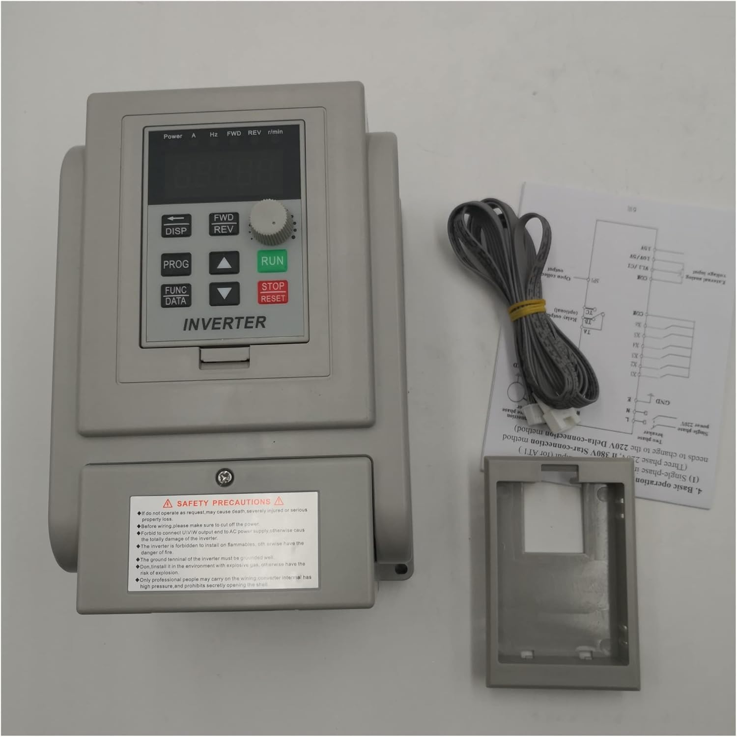
Figure 2.1: Front view of the XSY-AT1 inverter with safety label. Always observe all warnings.
3. Product Overview
The Suuim XSY-AT1 series VFD is available in various power ratings, including 1.5KW, 2.2KW, and 4.0KW, designed for single-phase 220V input and three-phase 220V output. It provides precise control over motor speed and torque.
3.1 Model Variants
While the core functionality remains consistent, different models and branding may feature slight variations in appearance or control panel layout.

Figure 3.1: ZW-AT1-1500X variant with standard control panel.

Figure 3.2: ZW-BT1 variant with JOG button on control panel.

Figure 3.3: 'CoolClassic' branded 1.5KW inverter variant.
4. Setup
4.1 Installation Environment
- Install the inverter in a well-ventilated area, away from direct sunlight, heat sources, and moisture.
- Ensure sufficient clearance around the unit for proper heat dissipation.
- Mount the inverter vertically on a stable, non-flammable surface.
4.2 Wiring Instructions
Correct wiring is critical for safe and proper operation. Refer to the terminal labels on the inverter.

Figure 4.1: Rear view showing terminal block and model information.

Figure 4.2: Close-up of wiring terminals.
- Ground (GND): Connect the ground terminal to a reliable earth ground. This is essential for safety.
- Input Power (L, N): Connect the single-phase 220V AC power supply to the 'L' and 'N' terminals. Ensure the input voltage matches the inverter's rating.
- Motor Output (U, V, W): Connect the three-phase motor's power cables to the 'U', 'V', and 'W' terminals. The phase sequence may affect motor rotation direction; if incorrect, swap any two output phases (e.g., U and V).
- Control Terminals: (If applicable) Some models may have additional terminals for external control signals (e.g., start/stop, speed reference, fault output). Refer to the specific model's detailed wiring diagram for these connections.
5. Operating Instructions
5.1 Control Panel Overview
The control panel typically includes a digital display, function buttons, and a rotary knob for parameter adjustment.
- Display: Shows operating frequency, output current, voltage, and parameter values.
- FWD/REV: Changes the motor's rotation direction (Forward/Reverse).
- DISP: Toggles between different display parameters.
- PROG: Enters/exits parameter setting mode.
- FUNC/DATA: Selects parameters or confirms data entry.
- RUN: Starts the motor.
- STOP/RESET: Stops the motor or clears fault indications.
- Rotary Knob (Potentiometer): Adjusts frequency or parameter values.
5.2 Basic Operation
- Power On: After ensuring all wiring is correct and secure, apply single-phase 220V power to the inverter. The display will illuminate.
- Set Frequency: Use the rotary knob to adjust the desired output frequency. The display will show the current frequency setting.
- Start Motor: Press the RUN button to start the motor. The motor will accelerate to the set frequency.
- Stop Motor: Press the STOP/RESET button to stop the motor. The motor will decelerate and stop.
- Change Direction: While the motor is stopped, press FWD/REV to toggle the rotation direction. Then press RUN.
5.3 Parameter Settings
The inverter has various programmable parameters to customize its operation. Refer to the detailed parameter list in the full product manual (if provided separately) for advanced settings such as acceleration/deceleration times, maximum frequency, motor parameters, etc.
- Press PROG to enter parameter setting mode.
- Use the rotary knob or arrow buttons (if available) to navigate through parameters.
- Press FUNC/DATA or OK to select a parameter for editing.
- Adjust the parameter value using the rotary knob or arrow buttons.
- Press FUNC/DATA or OK again to save the new value.
- Press PROG to exit parameter setting mode.
6. Maintenance
- Regular Cleaning: Keep the inverter clean and free from dust. Use a soft, dry cloth. Do not use liquid cleaners.
- Fan Inspection: Periodically check the cooling fan for obstructions and ensure it operates freely. Clean any dust buildup on the fan blades and heatsink.
- Terminal Check: Regularly inspect all wiring terminals for tightness. Loose connections can cause overheating or intermittent operation.
- Environmental Check: Ensure the operating environment remains within specified temperature and humidity ranges.
7. Troubleshooting
This section outlines common issues and potential solutions. For complex problems, contact technical support.
| Problem | Possible Cause | Solution |
|---|---|---|
| Inverter does not power on | No input power; faulty wiring; internal fuse blown. | Check power supply and connections. Verify input voltage. Consult a qualified technician for internal inspection. |
| Motor does not run | Inverter not in RUN mode; incorrect frequency setting; motor wiring error; motor fault. | Press RUN button. Adjust frequency. Check U, V, W wiring to motor. Test motor independently if possible. |
| Motor runs in wrong direction | Incorrect FWD/REV setting; motor phase sequence reversed. | Press FWD/REV button. Swap any two motor output phases (U, V, or W). |
| Overcurrent fault (OC) | Motor overload; short circuit in motor wiring; rapid acceleration/deceleration. | Reduce motor load. Check motor and wiring for shorts. Increase acceleration/deceleration times in parameters. |
| Overvoltage fault (OV) | Input voltage too high; motor regeneration during deceleration. | Verify input voltage. Increase deceleration time. Consider adding a braking resistor if regeneration is severe. |
| Undervoltage fault (UV) | Input voltage too low; power supply instability. | Check input power supply voltage. Ensure stable power. |
8. Specifications
| Feature | Description |
|---|---|
| Brand | Suuim |
| Model Series | XSY-AT1 (also ZW-AT1, ZW-BT1 variants) |
| Power Ratings | 1.5KW, 2.2KW, 4.0KW (depending on specific model) |
| Input Voltage | Single-phase 220V AC |
| Output Voltage | Three-phase 220V AC |
| Output Frequency Range | Typically 0-400Hz (adjustable) |
| Control Method | V/F control |
| Protection Features | Overcurrent, Overvoltage, Undervoltage, Overheat, Overload, Short Circuit |
| Cooling Method | Forced air cooling |
| Operating Temperature | Typically -10°C to 40°C |
| Humidity | Less than 90% RH (non-condensing) |
9. Warranty and Support
For warranty information, technical support, or service inquiries, please refer to the documentation provided with your purchase or contact your retailer. Keep your purchase receipt as proof of purchase.


