1. Introduction
The Algo 8028G2 is a SIP-based Voice over IP (VoIP) secure door/gate access control intercom system designed for indoor and outdoor environments. This system replaces the previous 8028 model and introduces enhanced features such as PoE+, Secure SIP, and a RESTful API. The 8028G2 includes a remotely located control unit for increased security, preventing tampering at the door access point. It is NEMA 3R rated for outdoor/indoor use and features a door control relay compatible with most door release, gate activation, or access control panels.
Additionally, the system offers low current programmable inputs and outputs on both the control unit and intercom station. These can be used for door sensing, door unlock switches, door unlock overrides, auxiliary call buttons, or to indicate telephone status (e.g., ringing or in-use).
Key Features:
- Indoor / Outdoor Weather-resistant SIP-based intercom with relay controller.
- Network managed and supervised SIP endpoint; requires Power over Ethernet (PoE).
- Supports PoE IEEE 802.3af or PoE+ IEEE 802.3at (if 24V 0.5A strike power is required).
- Door station can utilize existing twisted pair wiring for retrofitting older analog intercoms.
- Configuration via user-friendly web-based Graphical User Interface (GUI) or auto-provisioning.
2. Package Contents
The Algo 8028G2 kit includes the following components:
- Algo 8028G2 Controller Unit
- Algo 8028G2 Intercom Station with Stainless Steel Faceplate
- Surface Mount Bracket
- Mounting Gaskets for outdoor installation
3. Setup and Installation
Installation requires familiarity with computer networking and Voice over IP (VoIP) devices. Configuration is typically performed via a web-based graphical user interface or provisioning.
3.1. Component Overview

Figure 3.1.1: Algo 8028G2 Controller Unit (Front View)
This image shows the front panel of the Algo 8028G2 controller unit, featuring a reset button, an Ethernet port, and four status indicator LEDs with corresponding icons for power, phone, network, and lock status.
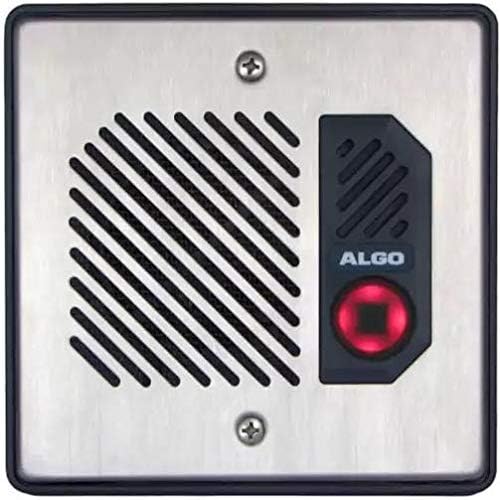
Figure 3.1.2: Algo 8028G2 Controller Unit (Rear View)
This image displays the rear panel of the Algo 8028G2 controller unit, which includes an auxiliary power input (24V 0.6A), a 24V output terminal block, a door sense input terminal block, and an auxiliary output terminal block.

Figure 3.1.3: Algo 8028G2 Intercom Station (Front View)
This image shows the front of the Algo 8028G2 intercom station with a stainless steel faceplate, featuring a speaker grille on the left and a call button with the Algo logo on the right.

Figure 3.1.4: Algo 8028G2 Intercom Station (Side View)
This image provides a side view of the Algo 8028G2 intercom station, revealing the internal terminal block labeled 'CTRL IN OUT' for control connections.
3.2. Power Requirements
The Algo 8028G2 is powered via Power over Ethernet (PoE). Ensure your network switch or PoE injector supports IEEE 802.3af or IEEE 802.3at (PoE+). If PoE is not available, a separate PoE injector must be used.
3.3. Controller Unit Placement
The controller unit must be installed indoors in a secure location. Its remote placement enhances security by isolating critical control components from potential tampering at the door station.
3.4. Intercom Station Placement
The intercom station is rated for both indoor and outdoor environments. It can be surface mounted using the included bracket or flush mounted into a double gang box (not included). Mounting gaskets are provided for outdoor installations to ensure weather resistance.

Figure 3.4.1: Intercom Station Dimensions and Mounting Options
This diagram illustrates the dimensions of the Algo 8028G2 intercom station in millimeters and inches, along with exploded views for both surface mount and flush mount installations, detailing components like the surface mount bracket, main housing assembly, and faceplate.
3.5. Wiring Connections
The door control relay can be connected to various door release, gate activation systems, or access control panels. Additionally, the low current programmable inputs and outputs can be wired for specific functions such as door sensing, door unlock switches, or auxiliary call buttons. Refer to the manufacturer's detailed wiring diagrams for specific connection instructions.
The relay port can also connect to Algo AR26LPW PoE strobes, Algo 1127 or 1128 strobes, or trigger remote Algo SIP Ringers & Strobes over the network.
4. Operating Instructions
Once installed and configured, the Algo 8028G2 functions as a secure SIP-based intercom system.
4.1. Making a Call
To initiate a call, a visitor presses the call button on the intercom station. The system will then dial the pre-configured SIP extension or group. The recipient can answer the call via their SIP phone or softphone.
4.2. Door/Gate Release
During an active call, the recipient can activate the door or gate release mechanism by entering a specific DTMF (Dual-Tone Multi-Frequency) code on their phone keypad. This code is configured during the system setup.
4.3. Status Indicators
The controller unit features LED indicators that provide visual feedback on the system's status:
- Power LED: Indicates the power status of the unit.
- Phone LED: Indicates SIP registration and call status.
- Network LED: Indicates network connectivity.
- Lock LED: Indicates the status of the door/gate lock relay.
5. Maintenance
Regular maintenance ensures the longevity and optimal performance of your Algo 8028G2 system.
5.1. Cleaning
For the intercom station, especially in outdoor environments, periodically clean the stainless steel faceplate with a soft, damp cloth. Avoid abrasive cleaners or solvents that could damage the finish or electronic components. Ensure no moisture enters the speaker grille or call button.
5.2. Firmware Updates
Algo regularly releases firmware updates to improve performance, add features, and address security vulnerabilities. It is recommended to check the manufacturer's website periodically for the latest firmware and follow their instructions for updating the device. Firmware updates are crucial for maintaining system security and compatibility.
5.3. Inspection
Periodically inspect all wiring connections for signs of wear, corrosion, or damage. Ensure all mounting hardware is secure, especially for outdoor installations.
6. Troubleshooting
This section addresses common issues you might encounter with the Algo 8028G2.
6.1. No Power
- Check PoE: Ensure the Ethernet cable is properly connected to a PoE-enabled port on your switch or a PoE injector. Verify that the PoE source is active and providing power.
- Controller Unit: Confirm the Power LED on the controller unit is illuminated.
6.2. No Network Connectivity
- Cable Connection: Verify the Ethernet cable is securely connected to both the controller unit and the network switch.
- Network LED: Check if the Network LED on the controller unit is active (flashing or solid green/amber, depending on status).
- Network Configuration: Ensure the device has a valid IP address and can communicate with other devices on the network.
6.3. SIP Registration Failure
- Phone LED: If the Phone LED is not active, it indicates a SIP registration issue.
- SIP Server Settings: Verify that the SIP server address, user ID, password, and port settings are correctly configured in the device's web interface.
- Firewall: Ensure no firewall rules are blocking SIP traffic (UDP ports 5060/5061 and RTP ports).
6.4. Door/Gate Release Not Working
- Wiring: Check the physical wiring between the controller unit's relay output and the door/gate release mechanism.
- DTMF Code: Confirm the correct DTMF code is being entered from the receiving phone.
- Relay Configuration: Verify the relay settings in the device's web interface are correct.
6.5. Resetting the Device
If the device is unresponsive or requires a factory reset, locate the reset button on the front panel of the controller unit (refer to Figure 3.1.1). Use a paperclip or similar pointed object to press and hold the reset button for approximately 10 seconds until the LEDs change state, indicating a reset.
7. Specifications
| Feature | Specification |
|---|---|
| Brand | Algo |
| Model Number | 8028G2 |
| UPC | 850058188256 |
| Compatible Devices | Door Release Systems, Gate Activation Systems, Access Control Panels |
| Specific Uses For Product | Telephone, Access Control |
| Connector Type | Auxiliary, Ethernet (RJ45) |
| Finish Type | Stainless steel (Intercom Station) |
| Number of Ports | 1 (Ethernet) |
| Input Voltage | 24 Volts (Auxiliary Power) |
| Current Rating | 0.5 Amps (Auxiliary Power) |
| Nominal Power | 24 Watts |
| Power Plug Type | No Plug (PoE or terminal block for auxiliary power) |
| Item Weight | 1.12 Kilograms |
| Unit Count | 1.0 Count |
8. Warranty Information
Specific warranty terms and conditions for the Algo 8028G2 are provided by the manufacturer. Please refer to the documentation included with your product or visit the official Algo website for detailed warranty information and registration procedures. Keep your proof of purchase for warranty claims.
9. Support
For technical assistance, frequently asked questions (FAQs), and additional resources, please visit the official Algo Communications Products website. The website provides comprehensive support documentation, firmware updates, and contact information for customer service.
Website: www.algosolutions.com