1. Introduction
Thank you for choosing the PULME ANJ-SM-2200H Hybrid Solar Inverter. This all-in-one hybrid solar inverter and charger is designed to provide reliable power for various household and office loads. It integrates a pure sine wave inverter, an MPPT solar charger, and a battery charger into one unit, offering uninterruptible power support. This manual provides essential information for the safe installation, operation, and maintenance of your inverter.
2. Safety Instructions
Please read all instructions and cautionary markings on the unit, this manual, and the battery before using the unit. Failure to follow these instructions may result in electric shock, fire, or severe injury.
- Ensure proper grounding of the inverter.
- Do not disassemble the unit. Refer servicing to qualified personnel.
- Keep the inverter away from water, rain, snow, or any liquid.
- Do not operate the inverter in environments with flammable gases or materials.
- Ensure adequate ventilation around the inverter to prevent overheating.
- Always disconnect all power sources (AC, PV, Battery) before performing any maintenance or wiring.
- This device features multi-protection against overload, overheating, and short circuits.
3. Product Overview
3.1 System Diagram
The PULME ANJ-SM-2200H is designed to integrate seamlessly into a home solar power system, managing power flow from solar panels, battery storage, and AC loads.

Figure 3.1: Illustrative diagram showing the hybrid solar inverter connected to solar panels, a battery bank, and supplying power to a typical household.
3.2 Internal Components
The inverter's robust internal design ensures efficient power conversion and management. Key components include the MPPT charge controller, inverter circuitry, and protection modules.

Figure 3.2: View of the inverter's internal components, highlighting the quality of construction and layout.
3.3 Front Panel and Indicators
The front panel provides an LCD display for system status, function keys for settings, and LED indicators for quick status checks.

Figure 3.3: Detailed view of the inverter's front panel, showing the LCD display, function keys, and LED indicators for user interaction and system monitoring.
3.4 Connection Ports
The rear/side panel features all necessary connection terminals for AC input, AC output, battery, and PV input.
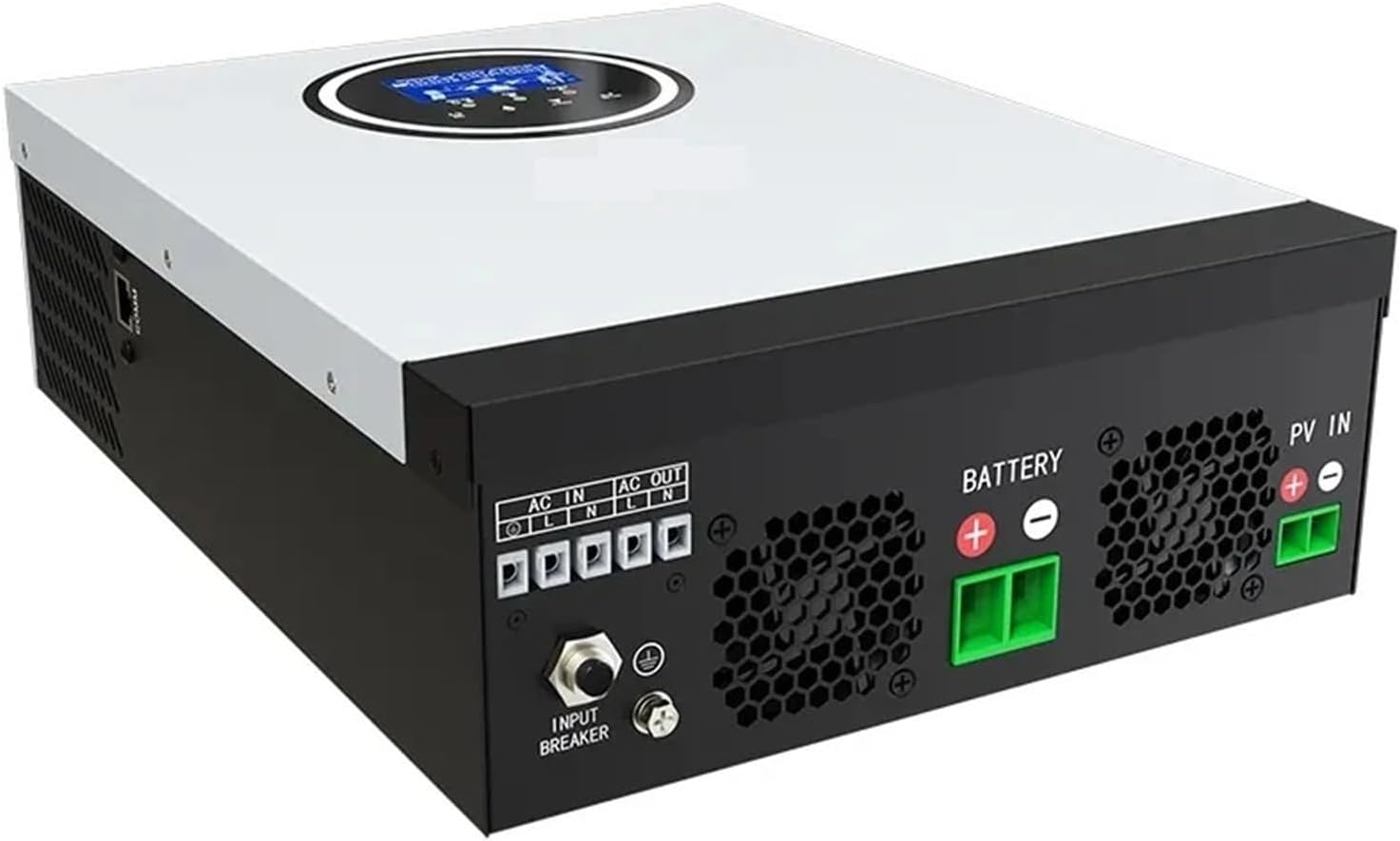
Figure 3.4: Overview of the inverter's connection ports, including AC input/output, battery terminals, PV input, and the input breaker.
3.5 Key Features
- New all-in-one hybrid solar inverter and charger.
- Multi-protection against overload, overheating, and short circuit.
- Provides access to a variety of household and office loads, including ovens, rice cookers, lamps, TVs, fans, and other AC loads.
- Features automatic restart during AC recovery and cold start function.
- Wide range of PV input allows adaptation to various types and sizes of solar panels, enhancing versatility and compatibility.
4. Setup and Installation
Proper installation is crucial for the safe and efficient operation of your inverter. Consult a qualified electrician for installation if you are unsure.
4.1 Mounting the Inverter
- Choose a suitable location that is dry, well-ventilated, and protected from direct sunlight and moisture.
- Ensure there is sufficient clearance around the inverter for proper airflow.
- Mount the inverter vertically on a sturdy surface using appropriate fasteners.
4.2 Wiring Connections
Refer to Figure 3.4 for connection port locations. Ensure all connections are secure and correctly polarized.
- Battery Connection: Connect the battery bank to the BATTERY terminals. Ensure correct polarity (+ to + and - to -). Use appropriate cable gauges.
- PV Input Connection: Connect the solar panel array to the PV IN terminals. Observe correct polarity. The wide PV input range allows flexibility in panel configuration.
- AC Output Connection: Connect your household or office loads to the AC OUT terminals.
- AC Input Connection: If using grid power as a backup or for charging, connect the AC grid supply to the AC IN terminals.
- Grounding: Connect the inverter's ground terminal to a reliable earth ground.
- Input Breaker: Ensure the input breaker is in the OFF position during wiring. Once all connections are verified, switch it to the ON position.
5. Operating Instructions
5.1 Initial Power-Up
- After completing all wiring and ensuring connections are secure, switch on the battery breaker (if applicable).
- Switch on the PV array breaker (if applicable).
- Switch on the AC input breaker (if applicable).
- Finally, switch on the inverter's input breaker (refer to Figure 3.4). The inverter will perform a self-test and the LCD display will illuminate.
5.2 LCD Display and Function Keys
The LCD display (Figure 3.3) shows real-time system status, including input/output voltage, battery charge level, load percentage, and operational mode. Use the function keys below the display to navigate through menus and adjust settings as needed. Consult the detailed settings guide (if provided separately) for advanced configurations.
5.3 Operational Modes
The inverter typically operates in various modes, such as:
- Solar Priority: Utilizes solar power first, then battery, and finally AC utility if needed.
- Utility Priority: Uses AC utility power primarily, with solar/battery as backup.
- Battery Priority: Discharges battery first, then switches to solar or utility.
The specific mode can be selected via the function keys and LCD menu.
6. Maintenance
Regular maintenance ensures the longevity and optimal performance of your inverter.
- Cleaning: Periodically clean the exterior of the inverter with a dry cloth. Ensure ventilation openings are free from dust and debris.
- Connections: Annually check all electrical connections (battery, PV, AC) for tightness and corrosion. Tighten any loose connections.
- Environment: Ensure the operating environment remains within specified temperature and humidity ranges.
- Battery Health: Monitor battery voltage and health regularly, especially if using lead-acid batteries.
7. Troubleshooting
This section provides solutions to common issues. For complex problems, contact technical support.
- Inverter Not Turning On: Check battery connections, battery voltage, and ensure all breakers (battery, PV, AC, inverter input) are in the ON position.
- No AC Output: Verify that the inverter is powered on and not in a fault state. Check AC output wiring and ensure loads are not exceeding the inverter's capacity.
- Low Battery Charge: Check PV panel connections and ensure they are clean and receiving adequate sunlight. Verify MPPT charger operation via the LCD. Check AC input if using utility charging.
- Overload Warning: Reduce the connected load. The inverter has overload protection and may shut down to prevent damage.
- Overheat Warning: Ensure adequate ventilation around the inverter. Clean any dust from vents.
8. Specifications
| Feature | Specification |
|---|---|
| Brand | PULME |
| Model | ANJ-SM-2200H |
| Wattage | 2000 watts (2.2 kW) |
| Input Voltage (DC) | 12V (Battery) |
| Output Voltage (AC) | 220V |
| Waveform | Pure Sine Wave |
| PV Input Voltage (Max) | 450V |
| MPPT Charger Current (Max) | 80A |
9. Warranty and Support
For warranty information and technical support, please refer to the documentation provided with your purchase or contact your retailer. Keep your proof of purchase for warranty claims.