1. Important Safety Information
Read and understand all safety warnings and instructions before operating this equipment. Failure to follow these instructions may result in electric shock, fire, serious injury, or property damage. Keep this manual for future reference.
- Electrical Safety: This unit requires professional electrical installation. Ensure the power supply matches the chiller's requirements (voltage, phase, frequency) and is properly grounded. Disconnect power before any maintenance or service.
- Refrigerant Handling: This chiller uses R407 refrigerant. Only qualified and certified personnel should handle refrigerant. Improper handling can cause serious injury or environmental damage.
- Water Connections: Ensure all water connections are secure and leak-free. Use appropriate sealing materials.
- Ventilation: The chiller is air-cooled. Ensure adequate airflow around the unit for proper heat dissipation. Do not block air inlets or outlets.
- Environmental Conditions: Operate the chiller within the specified environmental temperature range (ambient temperature must be ≤ 40°C).
- Personal Protective Equipment (PPE): Wear appropriate PPE, such as safety glasses and gloves, when working with the chiller.
- Emergency Stop: Familiarize yourself with the location and operation of the emergency stop function, if applicable.
2. Product Overview
The VEVOR YSD-15RT is a 15-ton industrial air-cooled water chiller designed for efficient temperature control in various industrial applications. It features a high-performance 15HP Panasonic compressor, a 150L stainless steel water tank, and a micro-computer control system for precise operation.

Figure 2.1: Front and side view of the VEVOR YSD-15RT Industrial Water Chiller.
Key Components:
- Compressor: 15HP Panasonic compressor for reliable cooling.
- Condenser: Finned condenser for efficient heat exchange.
- Water Tank: Integrated 150L stainless steel water tank.
- Control System: Micro-computer control with LCD display.
- Protection System: Includes overload, high/low pressure, and automatic water replenishment.

Figure 2.2: Internal view highlighting the compressor, built-in water pump, and high/low pressure controls.
This image illustrates the core internal components responsible for the chiller's performance, including the 11.25 KW Panasonic motor, the built-in water pump, and the high and low pressure control systems. These elements work together to ensure rapid refrigeration and stable operation.

Figure 2.3: Details of the superior cooling system, including fans and finned condenser.
The cooling system features powerful fan engines and a premium finned condenser designed for large air volume and quick heat dissipation. The unit also includes a high-capacity water tank and security double fans, contributing to a cooling air volume of 15000 m³/h.
3. Specifications
| Parameter | Value |
|---|---|
| Model | YSD-15RT |
| Cooling Capacity | 15 Ton (38700 Kcal/h, 11.25 KW) |
| Compressor Power | 15 HP |
| Refrigerant | R407 |
| Water Tank Capacity | 150 Liters |
| Adjustable Temperature Range | 5°C to 25°C |
| Water Flow | 3.5 m³/h |
| Pipe Inlet/Outlet Nominal Diameter | DN50 |
| Tap Water Inlet Nominal Diameter | DN15 |
| Product Dimensions (D x W x H) | 30.7" x 63" x 67" (78cm x 160cm x 170cm) |
| Item Weight | 463 pounds (210 kg) |
| Environmental Temperature Limit | ≤ 40°C |

Figure 3.1: Product dimensions for installation planning.
This image provides a visual representation of the chiller's dimensions, indicating a height of 67 inches (170 cm), a width of 63 inches (160 cm), and a depth of 30.7 inches (78 cm). These measurements are crucial for proper site selection and installation.
4. Installation and Setup
4.1 Unpacking and Inspection
- Carefully unpack the chiller and inspect for any shipping damage. Report any damage to the carrier immediately.
- Verify all components listed in the packing list are present.
4.2 Site Selection
- Choose a location with adequate ventilation and clearance around the unit for proper airflow and maintenance access.
- Ensure the floor is level and capable of supporting the chiller's weight (463 lbs / 210 kg) when filled with water.
- The ambient temperature at the installation site must not exceed 40°C.
4.3 Electrical Connection
Professional installation is required for electrical connections.
- Ensure the main power supply is disconnected before making any electrical connections.
- Connect the chiller to a dedicated power circuit that matches the unit's voltage, phase, and current requirements.
- Proper grounding is essential for safety.
4.4 Water Connections
- Connect the process water inlet and outlet pipes to the chiller's DN50 ports.
- Connect the tap water inlet to the chiller's DN15 port for automatic water replenishment.
- Ensure all connections are tight and sealed to prevent leaks.
- Fill the internal 150L stainless steel water tank with clean water.

Figure 4.1: Rear view with water connection points.
This image displays the rear of the chiller, indicating the locations for the main water inlet and outlet (DN50) and the smaller tap water inlet (DN15) for automatic water replenishment. Proper connection of these ports is vital for the chiller's functionality.
4.5 Initial Checks
- Double-check all electrical and water connections.
- Ensure the water tank is filled to the appropriate level.
- Confirm there are no obstructions to airflow around the chiller.
5. Operation
5.1 Control Panel Overview
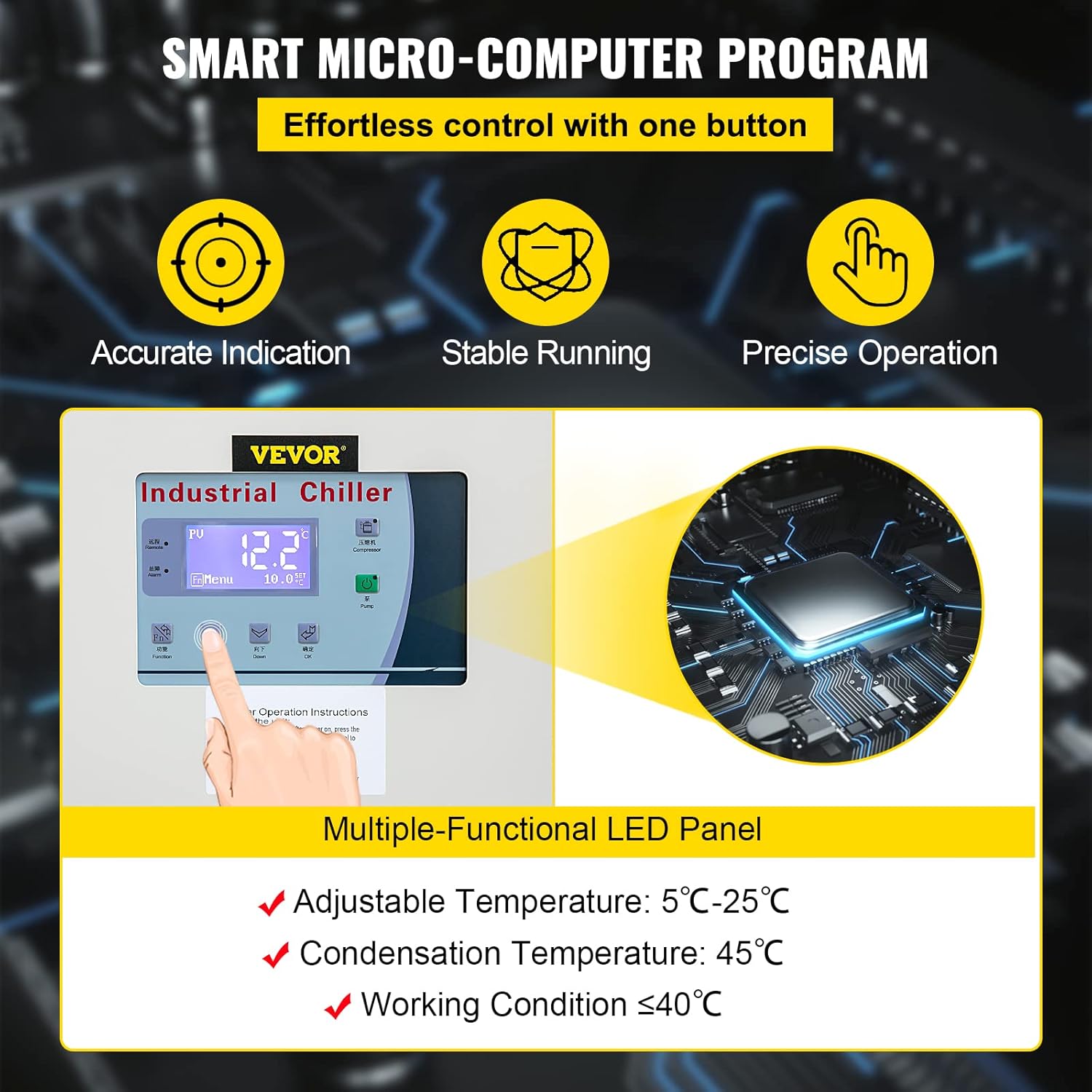
Figure 5.1: Smart Micro-Computer Control Panel.
The control panel features an intelligent LCD display and various buttons for managing the chiller's functions. It allows for accurate indication, stable running, and precise operation. The adjustable temperature range is 5°C to 25°C, with a condensation temperature of 45°C and optimal working conditions at ≤ 40°C ambient temperature.
- LCD Display: Shows current water temperature, set temperature, and operational status.
- Temperature Adjustment Buttons: Use these to increase or decrease the target water temperature.
- Power Buttons: For compressor and condenser control.
- Alarm Indicators: Display error codes or warnings.
5.2 Starting the Chiller
- Ensure all installation steps are completed and verified.
- Connect the main power supply to the chiller.
- Press the main power button on the control panel. The chiller will initiate its startup sequence.
5.3 Setting the Temperature
- Once the chiller is running, use the temperature adjustment buttons on the control panel to set the desired water temperature between 5°C and 25°C.
- The LCD display will show the set temperature and the current water temperature.
5.4 Monitoring Operation
- Regularly check the LCD display for operational status and any alarm messages.
- Listen for unusual noises or vibrations.
6. Maintenance
Regular maintenance is crucial for the longevity and efficient operation of your VEVOR water chiller.
6.1 Daily/Weekly Checks
- Water Level: Check the water level in the tank. The automatic water replenishment system will maintain the level, but manual verification is recommended.
- Leaks: Inspect all water connections and piping for any signs of leaks.
- Operational Sounds: Listen for any unusual noises from the compressor or fans.
6.2 Monthly/Quarterly Maintenance
- Condenser Fins: Clean the condenser fins to ensure optimal heat exchange. Use a soft brush or compressed air to remove dust and debris.
- Water Quality: Check the quality of the water in the tank. If necessary, drain and refill with clean water to prevent scale buildup and corrosion.
- Electrical Connections: With power disconnected, inspect all electrical connections for tightness and signs of wear.
6.3 Annual Maintenance (Professional Service Recommended)
- Refrigerant Level: Have a qualified technician check the refrigerant (R407) level and pressure. Recharge if necessary.
- Compressor Inspection: Professional inspection of the compressor for wear and efficiency.
- System Flush: Consider a professional system flush to remove any accumulated contaminants.
7. Troubleshooting
This section provides solutions to common operational issues. For problems not listed here or if issues persist, contact VEVOR customer support.
| Problem | Possible Cause | Solution |
|---|---|---|
| Chiller not starting | No power, emergency stop engaged, faulty wiring. | Check power supply, reset emergency stop, inspect wiring (professional). |
| Insufficient cooling | Low water level, dirty condenser, low refrigerant, high ambient temperature. | Check water level, clean condenser, check refrigerant (professional), ensure proper ventilation. |
| High/Low Pressure Alarm | Refrigerant leak, blocked lines, fan malfunction. | Contact qualified technician for inspection and repair. |
| Water Level Alarm | Low water in tank, faulty sensor. | Check and refill water tank, inspect sensor. |
| Unusual Noise/Vibration | Loose components, fan imbalance, compressor issue. | Inspect for loose parts, contact professional for internal component check. |

Figure 7.1: Overview of the professional protection system.
The chiller is equipped with a comprehensive protection system designed to ensure secure operation. This includes phase loss and reverse protection, motor overload protection, high and low pressure protection, automatic water replenishment, coil overheating protection, and icing-proof protection. These features help prevent damage and ensure reliable performance.
8. Warranty and Support
For warranty information, technical assistance, or to order replacement parts, please contact VEVOR customer service. Refer to your purchase documentation for specific warranty terms and contact details.
You can typically find support information on the official VEVOR website or through your original point of purchase.