1. Introduction
This manual provides comprehensive instructions for the DIYmalls ESP32-2432S032C-I 3.2 inch ESP32 Display with Capacitive Touch Screen. It covers product features, setup procedures, operational guidelines, programming information, specifications, maintenance, and troubleshooting to ensure optimal use of your development board.
2. Product Overview
2.1 Key Features
- Integrated ESP-32 ESP32 development board with a 3.2 inch capacitive touch display.
- IPS display technology (ST7789) offering wider viewing angles and enhanced color accuracy compared to traditional TN displays.
- Supports code upload via Arduino IDE or ESP32 flash tools.
- Includes a TF card slot, supporting cards up to 32GB.
- Equipped with interfaces for speaker, battery, and extended I/O.
2.2 What's in the Box
The package includes the following components:
- 1x ESP32 IPS Capacitive Touch Screen (3.2 inch)
- 1x Dupont female to 1.25mm wire
- 1x 2-pin 1.25mm cable (for speaker or battery interface)

Image 2.2.1: The DIYmalls ESP32-2432S032C-I display module shown with the included Dupont female to 1.25mm wire and 2-pin 1.25mm cable.
2.3 Component Identification
Familiarize yourself with the various components and interfaces on the development board:
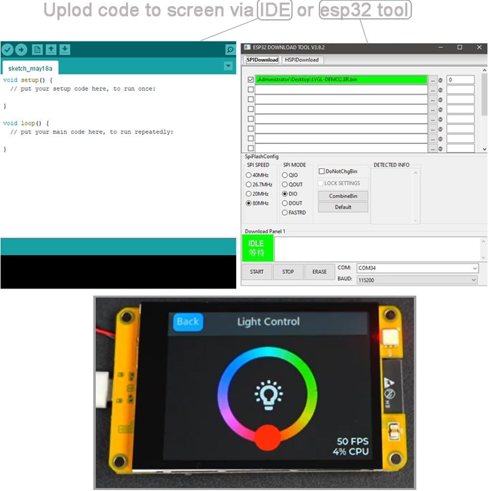
Image 2.3.1: Detailed view of the ESP32-2432S032C-I board with key components labeled, including the ESP-WROOM-32 module, TF card slot, Type-C USB port, boot and reset buttons, battery and speaker connectors, and extended I/O pins.
- ESP-WROOM-32: The core Wi-Fi and Bluetooth module.
- Boot Button: Used for entering bootloader mode for firmware flashing.
- Reset Button: Resets the ESP32 module.
- Type-C USB Port: For power supply and data communication (programming).
- TF Card Slot: Supports MicroSD cards up to 32GB for data storage.
- 2p 1.25mm Battery Connector: For connecting an external lithium battery.
- Lithium Battery Switch Button: Controls power from the connected battery.
- 2p 1.25mm Speaker Connector: For connecting a small speaker.
- Extended I/O: General Purpose Input/Output pins for connecting external sensors and modules.
- Temperature/Humidity Sensor Interface: Dedicated pins for compatible sensors.
3. Setup
3.1 Initial Power-Up
- Connect the device to a power source using a USB Type-C cable. A standard 5V USB power adapter or a computer's USB port can be used.
- The display should power on and show a default demonstration program if pre-loaded.
3.2 Connecting Peripherals
- TF Card: Insert a MicroSD card (up to 32GB) into the TF card slot for additional storage. Ensure the card is formatted correctly (e.g., FAT32).
- Battery: Connect a compatible lithium battery to the 2-pin 1.25mm battery connector. Use the battery switch button to enable/disable battery power.
- Speaker: Connect a small speaker to the 2-pin 1.25mm speaker connector if audio output is required for your application.
- External Sensors/Modules: Utilize the Extended I/O pins and dedicated sensor interfaces to connect other components as per your project requirements. Refer to the board's pinout for specific connections.
4. Operating Instructions
4.1 Basic Interaction
The 3.2 inch IPS display features a capacitive touch screen, allowing for intuitive interaction with applications running on the ESP32 module.

Image 4.1.1: The display showing a graphical user interface for light control, demonstrating the visual capabilities and touch responsiveness.
- Touch: Use your finger to tap, swipe, and interact with on-screen elements.
- Responsiveness: The capacitive touch screen provides a responsive and smooth user experience.

Image 4.1.2: A finger interacting with a profile screen on the ESP32 display, demonstrating touch input for sliders and toggles.

Image 4.1.3: A finger typing on a virtual keyboard displayed on the ESP32 screen, illustrating text input capabilities via touch.
5. Programming Guide
5.1 Uploading Code
The ESP32-2432S032C-I can be programmed using the Arduino IDE or dedicated ESP32 flash tools.
- Install Drivers: Ensure necessary USB-to-serial drivers are installed on your computer.
- Connect: Connect the ESP32 board to your computer via the Type-C USB port.
- Arduino IDE Setup:
- Install the ESP32 board package in the Arduino IDE Board Manager.
- Select the correct board model (e.g., ESP32 Dev Module) and COM port from the Tools menu.
- Write or load your sketch.
- Click the 'Upload' button to flash the code to the ESP32. You may need to press and hold the 'Boot' button while pressing 'Reset' to enter programming mode, then release 'Boot' when the upload starts.
- ESP32 Flash Tool: For more advanced flashing options or specific firmware, use the ESP32 Download Tool.
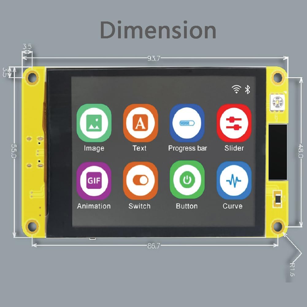
Image 5.1.1: A visual representation of the Arduino IDE interface for writing code and the ESP32 Download Tool for flashing firmware to the device.
5.2 Resources and Documentation
Due to the open-source nature of ESP32 development, extensive community-driven documentation, examples, and libraries are available online. Search for "ESP32-2432S032C-I projects" or "ESP32-Cheap-Yellow-Display" on platforms like GitHub and various electronics forums for detailed guides and sample code.
6. Specifications
Detailed technical specifications for the DIYmalls ESP32-2432S032C-I:
| Feature | Specification |
|---|---|
| Display Size | 3.2 inches |
| Display Type | IPS TFT LCD |
| Resolution | 240x320 pixels |
| Touch Screen | Capacitive |
| Controller IC | ST7789 |
| Microcontroller | ESP32 (ESP-WROOM-32 module) |
| Storage | TF card slot (up to 32GB) |
| Connectivity | Wi-Fi, Bluetooth |
| Power Input | USB Type-C (5V) or 2-pin 1.25mm battery connector |
| Dimensions | Approximately 93.7mm x 55.0mm (3.69 x 2.17 inches) |
| Item Weight | 3.2 ounces |
Image 6.1.1: A diagram illustrating the physical dimensions of the ESP32-2432S032C-I board in millimeters.
6.2 Schematic Diagram
For advanced users and developers, a schematic diagram of the board's circuitry is provided for detailed understanding of component connections and power distribution.
Image 6.2.1: Detailed schematic diagram showing the electrical connections and components of the ESP32-2432S032C-I development board.
7. Maintenance
- Cleaning: Use a soft, dry cloth to clean the display and board. Avoid abrasive materials or harsh chemicals.
- Storage: Store the device in a dry, dust-free environment away from extreme temperatures.
- Handling: Handle the board by its edges to avoid touching sensitive components or the display surface.
- Firmware Updates: Regularly check for updated firmware or libraries from the ESP32 community to ensure optimal performance and access to new features.
8. Troubleshooting
- Display Not Powering On: Ensure the USB Type-C cable is securely connected and the power source is active. If using a battery, check its charge and ensure the battery switch is in the 'on' position.
- Code Upload Failure: Verify that the correct board and COM port are selected in the Arduino IDE. Ensure necessary drivers are installed. Try pressing and holding the 'Boot' button while pressing 'Reset' during upload.
- Touch Screen Unresponsive: Check for any physical damage to the screen. Ensure your code properly initializes and handles touch input.
- Power Button Issues (when on battery): Some users have reported inconsistent behavior with the power button when operating on battery power. If experiencing issues, consider using the device primarily with a wired power supply or investigate community solutions for battery management.
- No Output on Speaker: Verify speaker connection and ensure your code is configured to output audio to the correct pins.
- TF Card Not Detected: Ensure the TF card is properly inserted and formatted (FAT32). Check your code for correct TF card initialization.
9. Warranty and Support
For specific warranty information, please refer to the purchase documentation or contact your retailer. For technical support and community resources, visit online forums and development communities dedicated to ESP32 and similar display modules. The DIYmalls brand store may also provide additional resources.
DIYmalls Brand Store: Visit DIYmalls Store on Amazon


