1. Introduction
This manual provides detailed instructions for the installation, operation, and maintenance of the Graigar Smartgen FPC615 Fire Pump Controller Module. The FPC615 is designed for controlling fire pump units, offering both automatic and manual start capabilities. It integrates advanced monitoring and protection features to ensure reliable performance of the genset.
2. Product Overview
The FPC615 controller features a robust design with a silicon panel and pushbuttons, ensuring durability in various temperature environments. Its 132x64 pixel LCD with backlight provides clear visual feedback, enhanced by improved wear and scratch resistance.
Key Features:
- Engine speed detection functionality.
- Three analog sensor inputs for water temperature, oil pressure, and oil temperature.
- Voltage sampling points for two battery packs and one battery charger.
- Three programmable digital input ports.
- Eight fixed relay output ports for Start 1, Start 2, Stop, Running, Over Speed, High Engine Temperature, Low Engine Temperature, and Low Oil Pressure.
- One fixed transistor output for High Raw Water Temperature and one programmable transistor output.
- Ability to switch between two battery packs for unit starting.
- Integrated protection functions for engine high water temperature and low oil pressure.
- Event log (up to 99 entries) and real-time clock.
- Three programmable maintenance functions with settable actions.
- Built-in multiple user-defined sensor curves.
- Parameters configurable from the front panel, retained upon power loss.
- Wide DC power supply range (8-35V) for diverse battery environments.
- IP55 waterproof security level for the front panel.
- Metal fixing clips for secure mounting in high-temperature conditions.

Figure 2.1: Front view of the FPC615 controller, showing the LCD display, control buttons, and indicator lights.
3. Setup and Installation
Proper installation is crucial for the reliable operation of the FPC615 controller. Ensure all connections are secure and follow local electrical codes.
Mounting:
The controller is designed for panel mounting. Use the provided metal fixing clips to secure the unit into a panel cutout of 186mm x 141mm. Ensure adequate ventilation around the unit.
Wiring Connections:
Refer to the wiring diagram on the back of the unit for all electrical connections. The FPC615 supports a DC supply voltage range of 8V to 35V. Connect the DC supply, W/L magnetic pickup, sensors, digital inputs, and output relays as indicated.
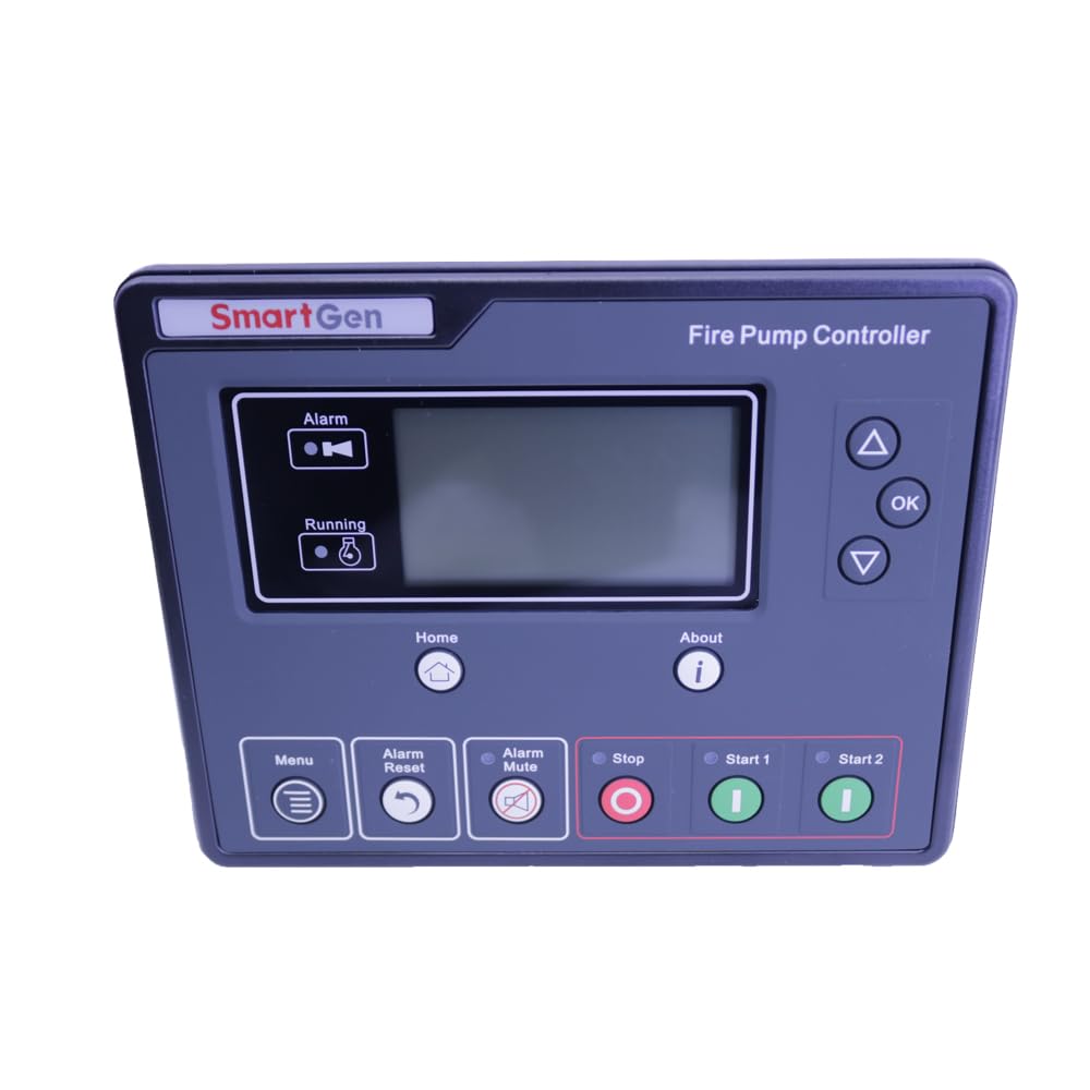
Figure 3.1: Back view of the FPC615 controller, illustrating the various wiring terminals for power, inputs, and outputs.
- DC Supply (Terminals 1-3): Connect the main DC power source.
- W/L Magnetic Pickup (Terminals 20-23): Connect for engine speed detection.
- Sensor Inputs (Terminals 25-30): Connect water temperature, oil pressure, and oil temperature sensors.
- Digital Inputs (Terminals 39-42): Connect programmable digital input signals.
- DC Input 0-40V (Terminals 43-46): Connect for battery pack and charger voltage sampling.
- Output Relays (Terminals 4-19, 47-49): Connect to the respective control circuits for start, stop, and alarm functions.
4. Operating Instructions
The FPC615 controller supports both automatic and manual operation modes.
Control Panel:
The front panel features an LCD display and several pushbuttons for control and navigation:
- Menu Button: Accesses the main menu for parameter settings and system information.
- Alarm Reset Button: Resets active alarms.
- Alarm Mute Button: Silences the audible alarm.
- Stop Button: Initiates a manual stop sequence for the unit.
- Start 1 / Start 2 Buttons: Initiates a manual start sequence for the unit.
- OK / Up / Down Buttons: Used for navigation and parameter adjustment within the menu.
Auto Mode:
In auto mode, the controller will automatically start the unit based on remote input signals. Ensure all necessary remote inputs are correctly configured and connected. The controller continuously monitors the genset status and initiates protection actions as needed.
Manual Mode:
To manually operate the unit, press the 'Start 1' or 'Start 2' button on the front panel. The unit will follow its programmed start sequence. Press the 'Stop' button to manually shut down the unit.
Monitoring:
The LCD displays real-time operational parameters, including engine speed, sensor readings, and battery voltages. Any active alarms or warnings will also be shown on the display.
5. Maintenance
The FPC615 controller includes three programmable maintenance functions. These functions allow users to set specific actions or reminders based on operational hours or other criteria. Refer to the controller's menu for configuring maintenance schedules and actions. Regular checks of wiring connections and sensor integrity are recommended.
6. Troubleshooting
The controller provides intelligent protection for the genset by initiating warning or shutdown alarms based on user-defined data protection thresholds. Information regarding alarms will be displayed on the LCD.
Common Alarms and Actions:
- High Engine Temperature: Check engine cooling system, coolant levels, and temperature sensor.
- Low Oil Pressure: Check engine oil level, oil pump, and oil pressure sensor.
- Over Speed: Check engine speed sensor and governor settings.
- High Raw Water Temperature: Check raw water cooling system and sensor.
- General Alarm: Consult the LCD for the specific alarm message and refer to the detailed troubleshooting guide in the full product manual (if available) or contact support.
Always address the root cause of an alarm before resetting it. If an issue persists, contact technical support.
7. Specifications
| Parameter | Value |
|---|---|
| Brand | Graigar |
| Model | FPC615 |
| Operation Panel | Silicon Rubber |
| Language Options | Chinese, English, and others |
| Digital Inputs | 3 |
| Analogue Inputs | 3 |
| Digital Outputs | 10 |
| Monitor Interface | LINK |
| Programmable Interface | LINK |
| RTC & Event Log | Yes |
| Scheduled Start/Stop | Yes |
| IP Protection Class (front panel) | IP65 |
| DC Supply Range | DC (8~35)V |
| Case Dimensions | 197mm x 152mm x 47mm |
| Panel Cutout Dimensions | 186mm x 141mm |
| Operating Temperature | (-25~+70)℃ |
| Material | Plastic |
| Included Components | Controller module |
8. Warranty and Support
For warranty information and technical support, please contact your authorized Graigar dealer or the manufacturer directly. Ensure to provide your product model number (FPC615) and purchase details when seeking assistance. Keep your purchase receipt as proof of purchase.