Treedix 5X5X5
Treedix 5x5x5 RGB LED Cube Light DIY Kit Instruction Manual
Brand: Treedix | Model: 5X5X5
1. Product Overview
The Treedix 5x5x5 RGB LED Cube Light DIY Kit is an electronic assembly kit designed for learning and creative projects. It features a 5x5x5 matrix of 125 individually addressable 5mm RGB LED beads. Each LED has four pins and is capable of emitting full-color light. The design utilizes a single-wire protocol for control, simplifying the circuitry.
This kit is ideal for enthusiasts interested in DIY electronics, programming, and creating custom lighting effects. It offers compatibility with various programmable controllers, including Arduino, Raspberry Pi, Teensy, T1000S, and K1000C.
2. Included Components
Before beginning assembly, please verify that all the following components are present in your kit:
- PCB boards
- RGB LED lights (125 pieces)
- Pin headers
- Copper columns

Image 2.1: All components included in the Treedix 5x5x5 RGB LED Cube DIY Kit.
3. Assembly Instructions
This kit requires self-assembly and soldering. Follow these steps carefully to construct your LED cube.
3.1 Understanding the PCB and LED Pins
Each PCB board is designed to hold 25 LEDs, forming one layer of the cube. The LEDs are 5mm RGB type with four pins. It is crucial to correctly identify the pin functions before soldering.

Image 3.1: Diagram showing the dimensions and pin assignments for the 5mm RGB LED. Pin 1: Digital In, Pin 2: GND, Pin 3: VIN, Pin 4: Digital Out.

Image 3.2: Close-up view of an LED slot on the PCB, indicating the corresponding pin functions (Digital In, GND, VIN, Digital Out).

Image 3.3: Pin specifications for the PCB board, showing VCC, GND, DIN, and DOUT connections.
3.2 Soldering LEDs to PCB Layers
- Carefully insert each LED into its designated slot on the PCB board, ensuring the correct pin orientation as indicated by the markings on the board and the LED diagram.
- Solder all four pins of each LED to the PCB. Ensure strong, clean solder joints to prevent connectivity issues.
- Repeat this process for all 25 LEDs on each of the five PCB layers.

Image 3.4: Visual guide for inserting LEDs into the PCB board.
3.3 Assembling the Cube Layers
Once all LEDs are soldered to their respective PCB layers, you will stack these layers to form the 5x5x5 cube structure. Use the provided copper columns to connect the layers.
- Align the first PCB layer (bottom layer) with four copper columns. Securely fasten the columns to the designated holes on the PCB.
- Place the second PCB layer on top of the copper columns, ensuring proper alignment. Solder or secure the layer to the columns.
- Repeat this process for the remaining layers until all five layers are stacked and secured, forming the cube.

Image 3.5: Animated demonstration of the LED cube layers.

Image 3.6: Animated demonstration of connecting the LED cube layers.
3.4 Wiring the Cube
The LED cube uses a single-wire protocol. Connect the Digital In (DIN) and Digital Out (DOUT) ports between layers and to your microcontroller.

Image 3.7: Diagram illustrating the wiring connections for the PCB, including Digital In, Digital Out, VIN, and GND.

Image 3.8: Close-up view of the wiring connections between LED cube layers, showing Digital In (DI) and Digital Out (DO) connections.
4. Operating Instructions
Once assembled, the LED cube can be connected to a compatible microcontroller for programming and operation.
4.1 Powering On and Initial Test
Connect the assembled LED cube to a compatible power source and microcontroller (e.g., Arduino, Raspberry Pi) using the VCC, GND, DIN, and DOUT ports. Ensure all connections are secure.

Image 4.1: The fully assembled LED cube connected to a power source and microcontroller for operation.
4.2 Programming Customization
The LED cube's individual LEDs can be controlled through programming. You can manipulate the color and brightness of each LED to create various lighting effects. The single-wire protocol simplifies control, often compatible with libraries like FastLED for Arduino.

Image 4.2: An example code snippet demonstrating how to program the LED cube using a compatible library.
4.3 Visual Demonstrations
Observe the various lighting patterns and color displays achievable with the Treedix 5x5x5 RGB LED Cube.
Video 4.1: A demonstration of the Treedix LED Cube Light DIY Kit displaying various colorful lighting effects and patterns.
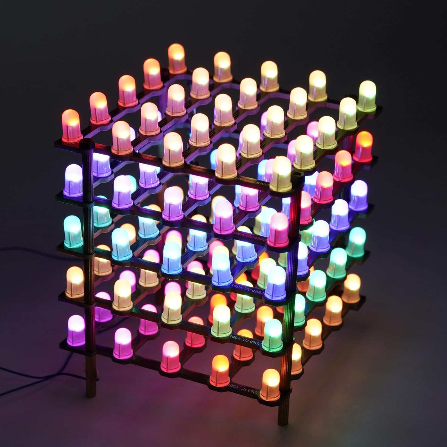
Image 4.3: The LED cube illuminated with a vibrant array of colors.
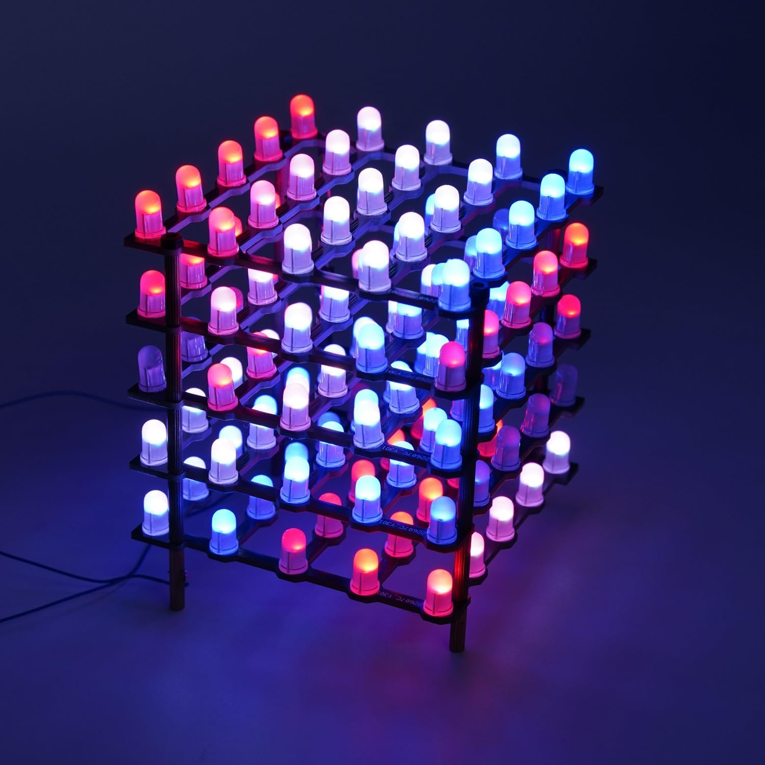
Image 4.4: The LED cube showcasing a pattern of red and blue lights.

Image 4.5: The LED cube demonstrating solid color displays in green, red, and blue.
5. Maintenance
To ensure the longevity and optimal performance of your Treedix LED Cube Light DIY Kit, follow these maintenance guidelines:
- Cleaning: Gently wipe the cube with a soft, dry cloth to remove dust. Avoid using liquid cleaners directly on the LEDs or PCB.
- Handling: Handle the assembled cube with care to prevent damage to the soldered connections or LEDs.
- Storage: Store the cube in a dry, cool environment away from direct sunlight and extreme temperatures.
- Inspecting Connections: Periodically check soldered joints for any signs of corrosion or loosening, especially if the cube is frequently moved.
6. Troubleshooting
If you encounter issues with your LED cube, refer to the following common problems and solutions:
- LEDs not lighting up:
- Check power connections (VCC, GND) to ensure they are correctly wired and receiving power.
- Verify all solder joints for the affected LEDs and PCB connections. Cold or incomplete solder joints can prevent LEDs from functioning.
- Ensure the data line (DIN/DOUT) is correctly connected to your microcontroller and that the programming code is running as expected.
- Incorrect colors or flickering:
- This often indicates a data signal issue. Check the DIN/DOUT connections between layers and to the microcontroller.
- Review your programming code for logic errors or incorrect LED addressing.
- Ensure your power supply is adequate for the number of LEDs. Insufficient power can lead to flickering or incorrect colors, especially at higher brightness levels.
- Cube not recognized by microcontroller:
- Confirm that the data pin specified in your code matches the physical pin connected on your microcontroller.
- Check for continuity in the data line wiring.
- Ensure the correct library (e.g., FastLED) is installed and properly configured in your development environment.
7. Specifications
| Feature | Detail |
|---|---|
| Model Name | 5X5X5 |
| LED Type | 5mm RGB, Individually Addressable |
| Number of LEDs | 125 (5x5x5 cube) |
| Control Protocol | Single-wire |
| Compatibility | Arduino, Raspberry Pi, Teensy, T1000S, K1000C, etc. |
| Power Source | Corded Electric (via microcontroller) |
| Material | Plastic (PCB), Copper (columns) |
| Item Weight | 0.26 Pounds |
| Item Dimensions (L x W x H) | 3.31"L x 3.31"W x 0.59"H (PCB layer, approximate) |
8. Warranty and Support
This product is returnable according to standard retail policies. For specific warranty details or technical support, please refer to the retailer's return policy or contact Treedix customer service through their official channels.
Ask a question about this manual
Ask about setup, troubleshooting, compatibility, parts, safety, or missing instructions. Manuals+ will review the question and use this page’s manual context to help answer it.