1. Introduction
This manual provides detailed instructions for the safe and effective operation, setup, and maintenance of your GuliTech FY6600 Dual Channel DDS Arbitrary Signal Generator. Please read this manual thoroughly before using the device to ensure optimal performance and to prevent damage.
2. Product Overview
The GuliTech FY6600 series is a high-performance dual-channel DDS (Direct Digital Synthesis) arbitrary waveform generator. It features a professional 14-bit high-speed D/A chip, a 250MSa/s sampling rate, and an 8192 * 14-bit waveform memory depth, allowing for precise and detailed signal generation. It includes a 2.4-inch TFT color LCD for clear display of waveforms and settings, and offers a wide range of functions including frequency measurement, VCO, and various modulation types.

Figure 2.1: Front view of the GuliTech FY6600 Dual Channel DDS Arbitrary Signal Generator. This image shows the device's display, control buttons, and output terminals.

Figure 2.2: Labeled diagram of the GuliTech FY6600 signal generator's front and rear panels. This diagram highlights key components including the 2.4-inch TFT Color LCD, Function Shortcut Buttons, Knob, Direction Button, Input Terminal, Output Terminal, Power Button, Menu Button, Power Switch, USB Communication Interface, 4 Channel TTL Output, AC Power Input, and Special Function Port.

Figure 2.3: Key features of the Digital DDS Dual-channel Signal Generator. This image displays the 2.4-inch TFT Color LCD with 320x240 resolution, 250MSa/s sample rate, 0.01S-999S sweep time, 1mVpp-24Vpp amplitude, and 8192 points * 14bits waveform length.
3. Setup
Follow these steps to set up your GuliTech FY6600 signal generator:
- Unpacking: Carefully remove the signal generator and all accessories from the packaging. Verify that all components listed in the packing list are present.
- Power Connection: Connect the provided AC power cord to the AC Power Input port on the rear panel of the device. Plug the other end into a standard electrical outlet.
- Power On: Press the Power Switch located on the rear panel to the 'ON' position. The device's LCD screen should illuminate.
- Initial Self-Test: The device will perform a brief self-test upon startup. Wait for the main interface to appear on the LCD.
- Output Connections: Connect your test leads or oscilloscope probes to the desired output channels (CH1 or CH2) on the front panel. Ensure connections are secure.
4. Operating Instructions
4.1 Basic Waveform Generation
- Select Channel: Press the CH1 or CH2 button to select the desired output channel. The active channel will be highlighted on the display.
- Select Waveform: Press the WAVE button. Use the knob to scroll through available waveforms (Sine, Square, Triangle, Pulse, Arbitrary, etc.) and press OK to confirm.
- Adjust Frequency: Use the knob to navigate to the frequency parameter. Rotate the knob to adjust the frequency value. Use the direction buttons to change the digit being adjusted for fine-tuning. Press OK to set.
- Adjust Amplitude: Navigate to the amplitude parameter. Rotate the knob to adjust the peak-to-peak amplitude (Vpp). Press OK to set.
- Enable Output: Ensure the output for the selected channel is enabled. This is typically indicated by an illuminated LED next to the channel button or an icon on the display.
4.2 Frequency Measurement
The FY6600 can also function as a frequency meter, allowing you to measure external signals.
- Connect Input: Connect the signal to be measured to the Input Terminal on the front panel.
- Select Measure Function: Press the MEAS button. The display will switch to frequency measurement mode.
- Read Measurement: The measured frequency will be displayed on the screen.
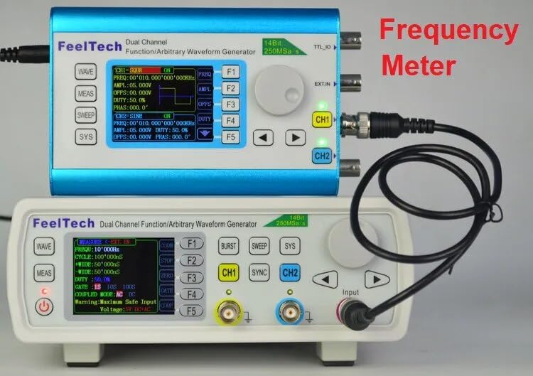
Figure 4.1: The FY6600 unit can function as a frequency meter, as shown here connected to another unit for measurement.
4.3 Dual Channel Operation
The FY6600 features two independent output channels (CH1 and CH2) that can generate different waveforms simultaneously or synchronized.
- Independent Control: Select CH1 or CH2 and configure its waveform, frequency, and amplitude independently using the steps described in Section 4.1.
- Synchronization: Use the SYNC button to synchronize the phase or frequency of the two channels if desired. Refer to the on-screen menu for synchronization options.
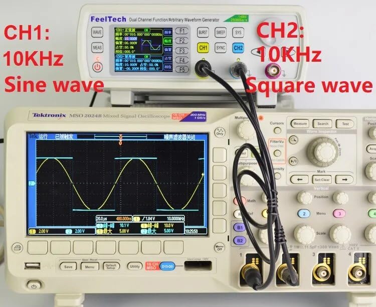
Figure 4.2: Example of dual-channel output: Channel 1 generating a 10KHz sine wave and Channel 2 generating a 10KHz square wave, displayed on an oscilloscope.
4.4 Modulation Functions
The FY6600 supports various modulation types, including AM (Amplitude Modulation).
- Select Channel: Choose the channel you wish to modulate.
- Access Modulation Menu: Press the MOD button to enter the modulation settings.
- Select Modulation Type: Use the knob to select the desired modulation type (e.g., AM, FM, PM, FSK, ASK).
- Configure Parameters: Adjust the modulation parameters such as modulation depth, frequency, and waveform using the knob and direction buttons.
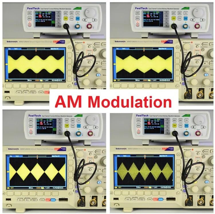
Figure 4.3: Various AM modulation waveforms generated by the FY6600, demonstrating its modulation capabilities as displayed on an oscilloscope.
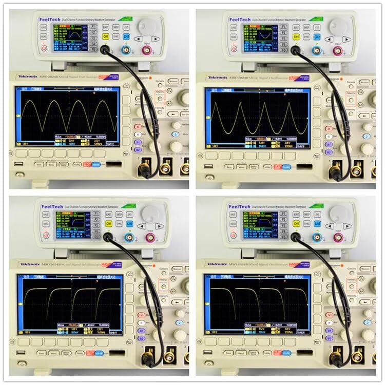
Figure 4.4: Further examples of complex waveforms and modulation types that can be generated by the FY6600, as seen on an oscilloscope.
5. Maintenance
5.1 Cleaning
To maintain the performance and appearance of your device:
- Ensure the device is powered off and disconnected from the power source before cleaning.
- Use a soft, dry cloth to wipe the exterior surfaces.
- For stubborn dirt, slightly dampen the cloth with water or a mild, non-abrasive cleaner. Avoid using harsh chemicals or solvents.
- Do not allow liquids to enter the device.
5.2 Storage
When not in use for extended periods:
- Store the device in a cool, dry place, away from direct sunlight and extreme temperatures.
- Keep it free from dust and moisture.
- It is recommended to store the device in its original packaging or a protective case.
6. Troubleshooting
This section addresses common issues you might encounter with your FY6600 signal generator.
| Problem | Possible Cause | Solution |
|---|---|---|
| Device does not power on | Power cord not connected; Power switch off; Faulty power outlet | Ensure power cord is securely connected. Turn power switch to 'ON'. Test power outlet with another device. |
| No output signal | Output channel not enabled; Incorrect amplitude setting; Faulty connection cable | Verify the selected channel's output is enabled. Check amplitude settings (ensure it's not 0Vpp). Inspect and replace connection cables if necessary. |
| Incorrect waveform displayed | Wrong waveform selected; Incorrect frequency/amplitude settings; Oscilloscope settings incorrect | Confirm the correct waveform type is selected. Double-check frequency and amplitude parameters. Adjust oscilloscope time base and voltage scale. |
| Frequency measurement inaccurate | Input signal too weak/strong; Incorrect input connection; External interference | Ensure the input signal is within the device's specified range. Verify the signal is properly connected to the Input Terminal. Minimize external noise sources. |
7. Technical Specifications
The following table details the technical specifications for the GuliTech FY6600 series signal generators.
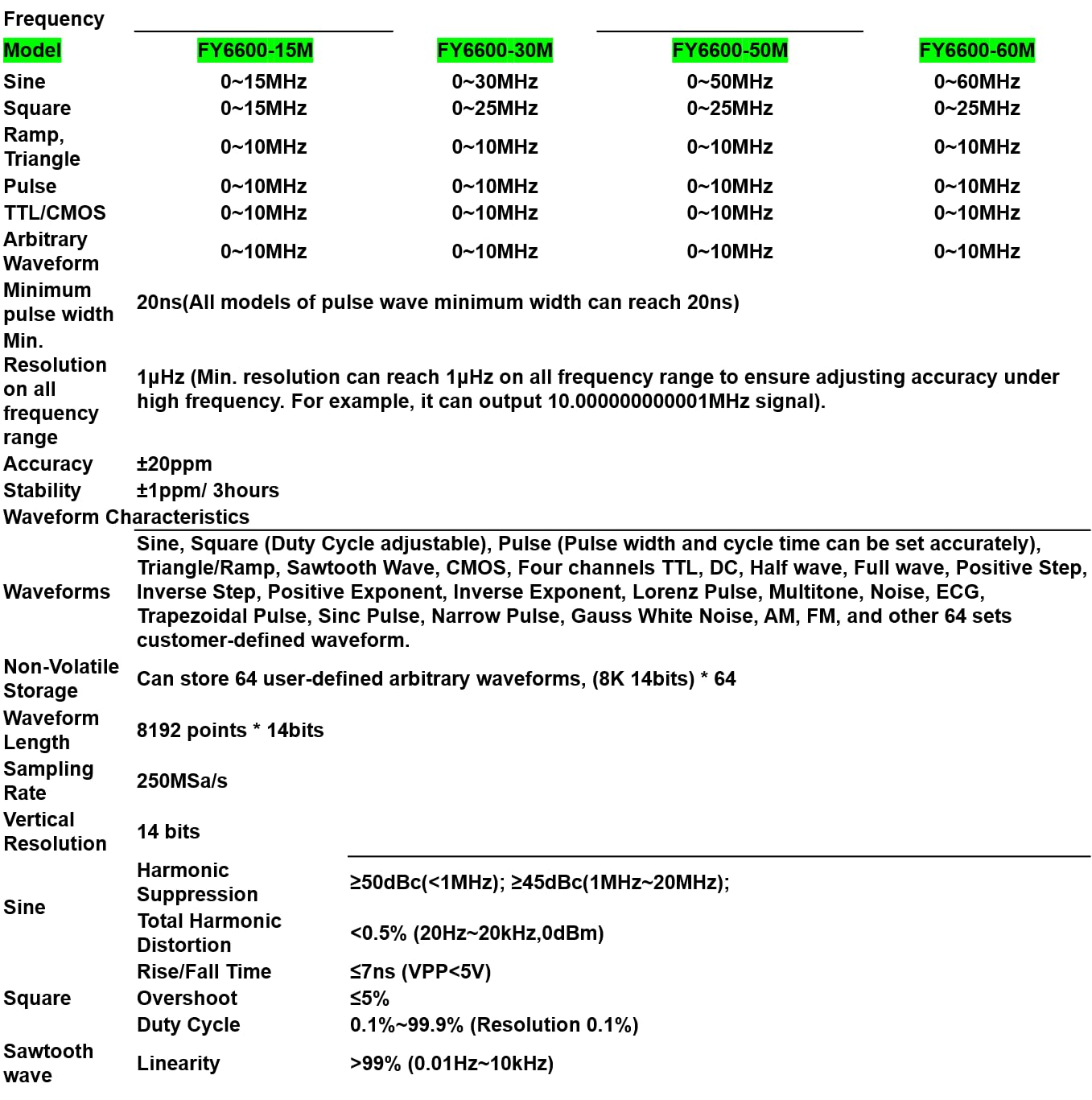
Figure 7.1: A comprehensive table outlining the technical specifications for different FY6600 models (15M, 30M, 50M, 60M), including frequency ranges for various waveforms, resolution, accuracy, stability, waveform characteristics, storage, sampling rate, vertical resolution, and harmonic suppression.
| Feature | Specification (FY6600 30M) |
|---|---|
| Model | FY6600 30M |
| Sine Wave Frequency Range | 0~30MHz |
| Square Wave Frequency Range | 0~25MHz |
| Ramp/Triangle Wave Frequency Range | 0~10MHz |
| Pulse Wave Frequency Range | 0~10MHz |
| TTL/CMOS Wave Frequency Range | 0~10MHz |
| Arbitrary Waveform Frequency Range | 0~10MHz |
| Minimum Pulse Width | 20ns |
| Frequency Resolution | 1µHz |
| Frequency Accuracy | ±20ppm |
| Frequency Stability | ±1ppm/3hours |
| Waveform Characteristics | Sine, Square (Duty Cycle adjustable), Pulse (Pulse width and cycle time can be set accurately), Triangle/Ramp, Sawtooth Wave, CMOS, Four channels TTL, DC, Half wave, Full wave, Positive Step, Inverse Step, Positive Exponent, Inverse Exponent, Lorenz Pulse, Multitone, Noise, ECG, Trapezoidal Pulse, Sinc Pulse, Narrow Pulse, Gauss White Noise, AM, FM, and other 64 sets customer-defined waveform. |
| Non-Volatile Storage | Can store 64 user-defined arbitrary waveforms (8K 14bits) * 64 |
| Waveform Length | 8192 points * 14bits |
| Sampling Rate | 250MSa/s |
| Vertical Resolution | 14 bits |
| Sine Harmonic Suppression | ≥50dBc (<1MHz); ≥45dBc (1MHz~20MHz) |
| Sine Total Harmonic Distortion | <0.5% (20Hz~20kHz, 0dBm) |
| Square Rise/Fall Time | ≤7ns (VPP<5V) |
| Square Overshoot | ≤5% |
| Square Duty Cycle | 0.1%~99.9% (Resolution 0.1%) |
| Sawtooth Wave Linearity | >99% (0.01Hz~10kHz) |
8. Warranty and Support
GuliTech products are designed for reliability and performance. This product comes with a standard manufacturer's warranty against defects in materials and workmanship. Please refer to the warranty card included with your purchase for specific terms and conditions, including the warranty period and coverage details.
For technical support, troubleshooting assistance, or warranty claims, please contact GuliTech customer service through the retailer where the product was purchased or visit the official GuliTech website for contact information. When contacting support, please have your product model number (FY6600 30M) and purchase date available.