1. Introduction
This manual provides comprehensive instructions for the safe and effective use of your Hantek DSO5072P Digital Storage Oscilloscope. It covers essential topics from initial setup and basic operation to advanced features, maintenance, and troubleshooting. Please read this manual thoroughly before operating the device to ensure optimal performance and safety.
2. Safety Information
Always observe the following safety precautions to prevent injury and avoid damage to the instrument or other connected devices.
- Hazardous Voltage: The device contains hazardous voltage inside. Do not remove the cover unless by specified personnel.
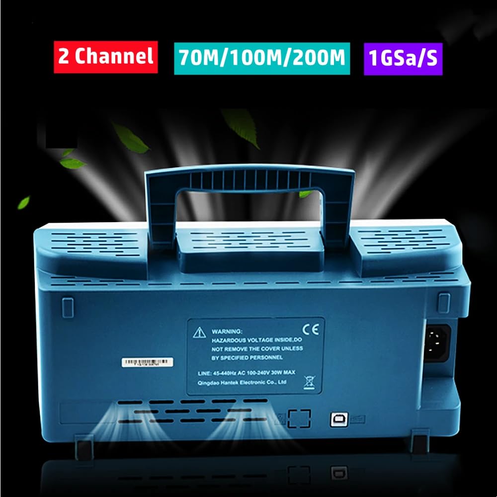
- Power Source: Ensure the oscilloscope is connected to a power source within the specified voltage range (AC 100-240V, 45-440Hz, 30W MAX).
- Grounding: Always ensure the oscilloscope is properly grounded to prevent electric shock.
- Environment: Operate the device in a dry, well-ventilated area, away from direct sunlight, high temperatures, and excessive dust.
- Probes: Use only probes rated for the voltage and current levels you intend to measure. Ensure probes are properly calibrated before use.
- Maintenance: Refer all servicing to qualified service personnel.
3. Package Contents
Verify that all items listed below are included in your package. If any items are missing or damaged, please contact your vendor.
- Hantek DSO5072P Digital Storage Oscilloscope Unit
- Power Cable
- USB Cable (Type A to Type B)
- Two (2) Oscilloscope Probes (with accessories)
- User Manual
- Software CD

The following video demonstrates the unboxing and initial overview of a similar Hantek oscilloscope model (MSO5102D), which shares many common features with the DSO5072P series.
4. Product Overview
Familiarize yourself with the main components and interfaces of your oscilloscope.
4.1 Front Panel
The front panel features the main display, function buttons, and control knobs for vertical, horizontal, and trigger settings. A USB host port is available for connecting USB storage devices, and a multi-pin connector is present for specific accessories or expansion.

4.2 Rear Panel
The rear panel includes the power input connector and a USB device port for PC connectivity, allowing for remote control and data sharing.
5. Setup
Follow these steps for initial setup of your oscilloscope.
5.1 Power Connection
- Connect the provided power cable to the power input on the rear panel of the oscilloscope.
- Plug the other end of the power cable into a grounded AC power outlet.
5.2 Probe Connection
- Connect the BNC connector of an oscilloscope probe to one of the Channel 1 (CH1) or Channel 2 (CH2) inputs on the front panel.
- Ensure the probe's ground clip is securely attached to the ground terminal of the circuit under test.
5.3 Powering On
Press the power button located on the front panel to turn on the oscilloscope. The device will undergo a boot sequence, and the display will show the Hantek logo before presenting the waveform interface.
6. Basic Operation
This section covers fundamental operations for capturing and analyzing waveforms.
6.1 Using the Test Signal
The oscilloscope provides a 1kHz square wave test signal, useful for calibrating probes and verifying basic functionality. Connect a probe to the dedicated test signal output on the front panel.
6.2 Adjusting Vertical and Horizontal Scales
- Vertical (Volts/Div): Use the VOLTS/DIV knob for the selected channel to adjust the vertical scale, changing the voltage represented by each vertical division on the screen.
- Horizontal (Time/Div): Use the TIME/DIV knob to adjust the horizontal scale, changing the time represented by each horizontal division.
- Position: Use the POSITION knobs for vertical and horizontal adjustments to move the waveform on the screen.
6.3 AutoSet Function
The AUTOSET button automatically adjusts the vertical, horizontal, and trigger settings to display a stable waveform. This is a quick way to get a view of your signal.

7. Specifications
Key technical specifications for the Hantek DSO5072P series oscilloscopes:
| Feature | DSO5202P | DSO5102P | DSO5072P |
|---|---|---|---|
| Bandwidth | 200MHz | 100MHz | 70MHz |
| Channels | 2 | ||
| Real-Time Sample Rate | 1GSa/s | ||
| Equivalent Sample Rate | 25GS/s | ||
| Record Length | 40K | ||
| Rise Time (BNC typical) | 1.8ns | 3.5ns | 5ns |
| Vertical Resolution | 8-bit resolution, all channel sampled simultaneously | ||
| Input Impedance | 1MΩ±2% || 20pF±3pF | ||
| Max Input Voltage | CAT II: 300VRMS (10×), Installation Category; CAT III: 150VRMS (1×) | ||
| Product Dimensions | 8.66 x 5.91 x 4.72 inches | ||
| Item Weight | 1.1 Pounds | ||

8. Maintenance
Proper maintenance ensures the longevity and accuracy of your oscilloscope.
- Cleaning: Use a soft, damp cloth to clean the exterior of the oscilloscope. Avoid abrasive cleaners or solvents that could damage the casing or screen.
- Storage: Store the device in a cool, dry environment, away from direct sunlight and extreme temperatures.
- Probe Care: Handle probes carefully. Avoid bending or stressing the cables. Store them properly to prevent damage to the tips and connectors.
- Ventilation: Ensure the ventilation openings on the device are not blocked to prevent overheating.
9. Troubleshooting
If you encounter issues with your oscilloscope, try the following common troubleshooting steps:
- No Power: Check the power cable connection to both the oscilloscope and the power outlet. Ensure the power button is pressed.
- No Display: If the power indicator is on but the screen is blank, try restarting the device. If the issue persists, contact support.
- No Signal on Screen: Verify that probes are correctly connected to both the oscilloscope input and the circuit under test. Check probe settings (e.g., 1X/10X attenuation). Use the AutoSet function.
- Unstable Waveform: Adjust the trigger level and mode. Ensure the horizontal time base is appropriate for the signal frequency.
- Incorrect Measurements: Calibrate your probes using the built-in test signal. Verify the probe attenuation setting on the oscilloscope matches the physical probe setting.
10. Warranty and Support
Hantek products are designed for reliability and performance. For warranty information, technical support, or service inquiries, please refer to the official Hantek website or contact your local distributor. Keep your purchase receipt as proof of purchase for warranty claims.