1. Introduction
The GuliTech FY6900 20M is a dual-channel Direct Digital Synthesis (DDS) function/arbitrary waveform generator, designed to produce accurate, stable, and low-distortion signals. It integrates a function signal generator, arbitrary waveform generator, pulse generator, noise generator, and frequency counter into a single compact unit. This device is suitable for electronic engineering, laboratory testing, and educational applications, providing a versatile tool for signal generation and measurement.
This manual provides essential information for the safe and effective operation of your FY6900 20M signal generator. Please read it thoroughly before use.
2. Product Overview
The FY6900 20M utilizes advanced DDS technology to ensure high signal accuracy and stability. Key features include:
- Dual-channel output for simultaneous generation of two independent signals.
- 2.4-inch (320*240) color display for clear parameter visualization.
- Up to 20MHz sine wave frequency (for 20M model), 250MSa/s sampling rate, and 14-bit vertical resolution.
- Ability to store up to 98 sets of user-defined functions/arbitrary waveforms.
- Desktop design with a durable ABS plastic case and wide AC 100-240V power supply compatibility.

Figure 2.1: Front view of the GuliTech FY6900 20M DDS Function Signal Generator, showing the display, control buttons, and output terminals.
2.1. Front and Rear Panel Layout
Understanding the layout of the front and rear panels is crucial for operating the device. Refer to the diagram below for component identification.

Figure 2.2: Detailed diagram illustrating the front panel controls (Power key, Menu softkeys, Function shortcut keys, Knob button, Direction keys, Output terminals, Input terminals) and rear panel connections (Special function port, 4 channel TTL output, USB communication interface, Power master switch, AC power input).
Front Panel Components:
- Power Key: Soft power button to turn the display on/off.
- Menu Softkeys: Context-sensitive buttons adjacent to the display for menu navigation and parameter selection.
- Function Shortcut Keys: Dedicated buttons for WAVE, MOD, SWEEP, COUNTER, VCO, and SYSTEM functions.
- Knob Button: Rotary encoder for adjusting parameter values.
- Direction Keys (Left/Right): Used to select digits or navigate menus.
- OK Button: Confirms selections.
- CH1/CH2 Output Terminals: BNC connectors for signal output from Channel 1 and Channel 2. These buttons also select the active channel and toggle output on/off.
- Counter Input Terminal: BNC connector for external frequency measurement.
Rear Panel Components:
- AC Power Input: Standard IEC power inlet for connecting the AC power cord.
- Power Master Switch: Hard power switch to completely disconnect the device from AC mains.
- USB Communication Interface: USB-B port for PC connectivity.
- 4 Channel TTL Output: Proprietary 8-pin connector for TTL level outputs.
- Special Function Ports: Includes SYNC IN, SYNC OUT, and VCO IN 0-5V BNC jacks for advanced synchronization and control.
3. Setup
Follow these steps to set up your FY6900 20M signal generator:
- Unpacking: Carefully remove the device and all accessories from the packaging. Verify that all components are present.
- Power Connection: Connect the provided AC power cord to the AC Power Input on the rear panel of the device and then to a suitable AC power outlet (100-240V).
- Initial Power On: Flip the Power Master Switch on the rear panel to the 'ON' position. Then, press the soft Power Key on the front panel to turn on the display.
- Output Connections: For signal generation, connect BNC cables from the CH1 or CH2 Output Terminals to your test equipment (e.g., oscilloscope, frequency counter).
- Counter Input (Optional): If using the frequency counter function, connect the external signal to be measured to the Counter Input Terminal.
4. Operating Instructions
This section details the basic operation of the FY6900 20M.
4.1. General Operation
- Channel Selection: Press the CH1 or CH2 button to select the desired channel for primary control. The display will highlight the parameters for the selected channel.
- Channel On/Off: A long press (approximately 1 second) on the CH1 or CH2 button will toggle the output of that channel on or off. The button's illumination indicates the channel's active status.
- Parameter Adjustment:
- Use the Function Shortcut Keys (e.g., WAVE, MOD) or Menu Softkeys to select the parameter you wish to adjust (e.g., frequency, amplitude, offset, duty cycle).
- Use the Left/Right Direction Keys to select the specific digit or field of the parameter.
- Rotate the Knob Button to change the value of the selected digit or field.
- Press the OK button to confirm the setting, if applicable.
4.2. Waveform Generation
To generate a waveform:
- Press the WAVE function button.
- Use the Menu Softkeys to select the desired waveform type (e.g., Sine, Square, Triangle, Pulse, Arbitrary).
- Adjust parameters such as Frequency (FREQ), Amplitude (AMPL), Offset (OFFSET), and Duty Cycle (DUTY) using the method described in Section 4.1. Note the frequency limits for different waveform types as detailed in the specifications.
- Ensure the desired channel's output is enabled by pressing its CH button until it illuminates.

Figure 4.1: The FY6900 20M generating a 15MHz sine wave, displayed on an external oscilloscope.
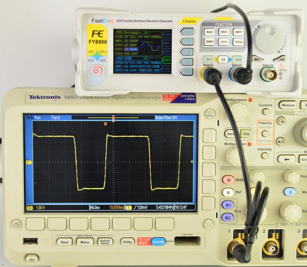
Figure 4.2: The FY6900 20M generating a square wave, displayed on an external oscilloscope.
4.3. Frequency Counter Function
The FY6900 20M includes a built-in frequency counter:
- Press the COUNTER function button.
- Connect the external signal you wish to measure to the Counter Input Terminal on the front panel.
- The display will show the measured frequency. This function can be used concurrently with signal generation on CH1 and CH2.
4.4. Other Functions (MOD, SWEEP, VCO, SYSTEM)
The device also supports modulation (MOD), sweep (SWEEP), voltage-controlled oscillation (VCO), and system settings (SYSTEM). Refer to the detailed online manual for specific instructions on these advanced functions.
5. Maintenance
Proper maintenance ensures the longevity and reliable performance of your FY6900 20M.
- Cleaning: Use a soft, dry cloth to clean the exterior of the device. Do not use abrasive cleaners or solvents. Ensure no liquids enter the device.
- Storage: Store the device in a clean, dry environment, away from direct sunlight, extreme temperatures, and high humidity.
- Safety: Always disconnect the power cord before cleaning or if the device will not be used for an extended period. Do not attempt to open the casing, as there are no user-serviceable parts inside. Refer all servicing to qualified personnel.
6. Troubleshooting
If you encounter issues with your FY6900 20M, refer to the following common problems and solutions:
- Device does not power on:
- Ensure the AC power cord is securely connected to both the device and the power outlet.
- Verify that the Power Master Switch on the rear panel is in the 'ON' position.
- Press the soft Power Key on the front panel.
- No signal output from CH1/CH2:
- Check if the respective channel (CH1 or CH2) is enabled (its button should be illuminated). If not, long-press the button to activate it.
- Verify that the amplitude setting is not zero.
- Ensure output cables are correctly connected and not damaged.
- Confirm that the connected test equipment is properly configured to receive the signal.
- Incorrect waveform or frequency:
- Double-check all parameter settings (waveform type, frequency, amplitude, offset, duty cycle) on the device's display.
- Ensure the selected waveform type is within its specified frequency range.
For further assistance, please consult the manufacturer's official support resources.
7. Specifications
The following table outlines the key technical specifications for the GuliTech FY6900 20M DDS Function Signal Generator.
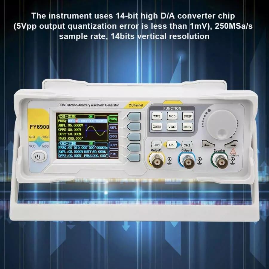
Figure 7.1: Technical specifications table for the FY6900 series, highlighting the 20M model.
| Characteristic | Specification (FY6900-20M) |
|---|---|
| Product Model | FY6900-20M |
| Frequency Range of Sine Wave | 0 ~ 20MHz |
| Frequency Range of Square Wave | 0 ~ 15MHz |
| Frequency Range of Other Waves | 0 ~ 10MHz |
| Minimum Adjustable Width of Pulse Wave | 20ns |
| Minimum Frequency Resolution | 1µHz |
| Waveform Length | 8192 points (8K points) * 14Bits |
| Waveform Sampling Rate | 250MSa/s |
| Vertical Resolution of Waveform | 14 Bits |
| Amplitude Range (peak to peak) | 1mVpp ~ 24Vpp (frequency ≤ 5MHz) 1mVpp ~ 20Vpp (5MHz < frequency ≤ 10MHz) 1mVpp ~ 10Vpp (10MHz < frequency ≤ 20MHz) 1mVpp ~ 5Vpp (frequency > 20MHz) |
| Amplitude Resolution | 1mV |
| Output Impedance | 50Ω ±10% (typical) |
| Bias Adjustment Range | frequency ≤ 20MHz: ±12V; frequency > 20MHz: ±2.5V |
| Minimum Bias Resolution | 1mV |
| Phase Adjustment Range | 0 ~ 359.99° |
| Minimum Phase Resolution | 0.01° |
| Display | 2.4-inch TFT color liquid crystal display |
| Interface | 115200 bps |
| Power Supply | AC100V ~ 240V |
| Environment Condition | Temperature: 0 ~ 40°C; Humidity: Less than 80% |
| Product Dimensions | 8.66 x 5.91 x 4.72 inches; 1.1 Pounds |
| Item Model Number | GL-FY6900 20M |
8. Support and Resources
For the most up-to-date information, detailed manuals, software downloads, and technical support, please visit the manufacturer's official website:
FeelTech Official Website (English)
This website provides comprehensive resources, including PDF manuals and guides on advanced features and PC connectivity.