1. Introduction
The Walfront QPM11 Normally Open Pressure Switch is designed for precise pressure monitoring and control in air-based systems. This device features a G1/8" adjustable bearing for installation and operates within a pressure range of 0.02 to 0.1 MPa. It is built to function reliably in temperatures from -5°C to 60°C, offering a high insulation voltage of 1500V and an IP54 rating for protection against dust and splashing water. With a maximum pulse rate of 200 cycles per minute and a lifespan of 1,000,000 cycles, the QPM11 provides consistent performance for industrial and scientific applications.
2. Product Overview
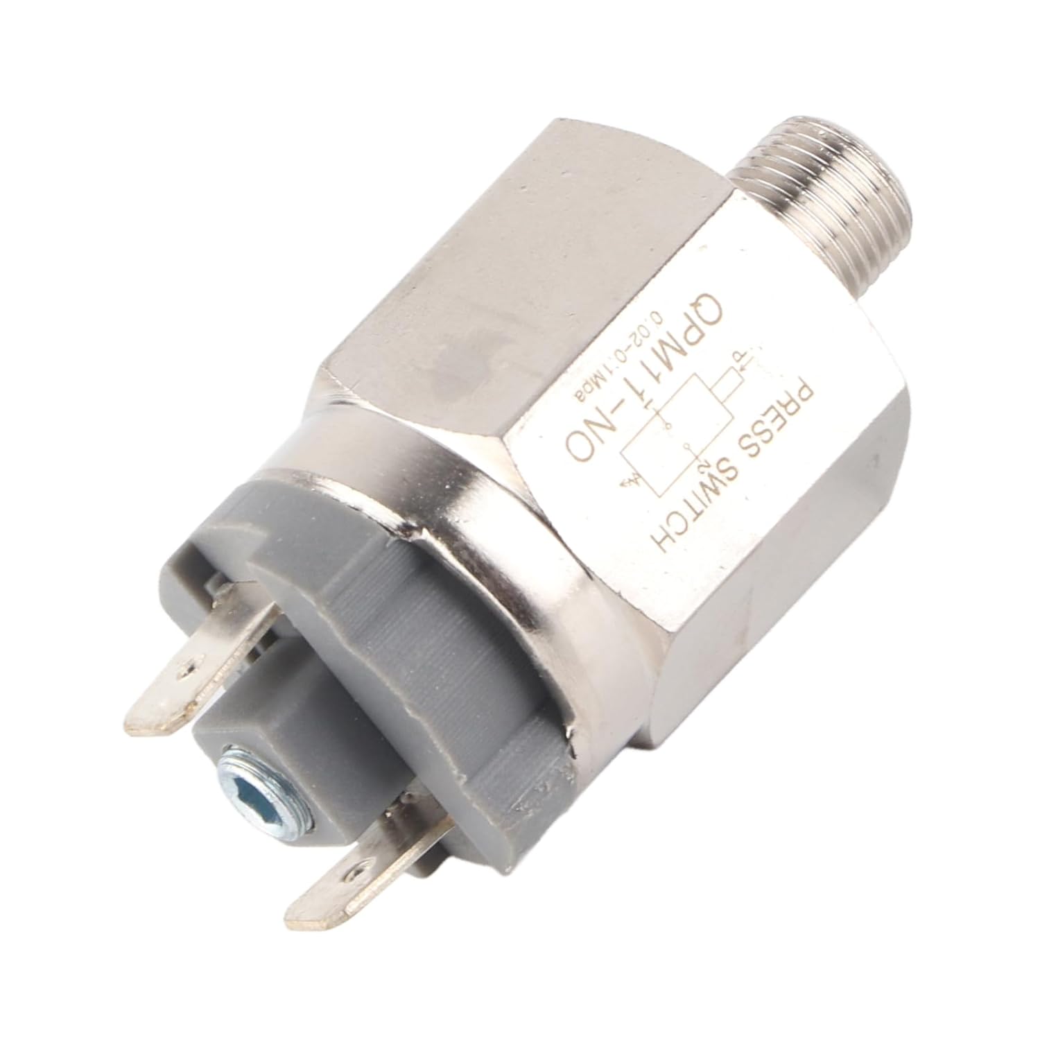
Figure 1: Overall view of the pressure switch, showing its compact design and main components.

Figure 2: Side view of the pressure switch, highlighting the G1/8" threaded connection for system integration.

Figure 3: Close-up view of the electrical terminals, where control circuit wiring is connected.

Figure 4: The pressure switch featuring a black protective cap, potentially covering the pressure adjustment mechanism.
3. Setup and Installation
Proper installation is crucial for the safe and accurate operation of the pressure switch.
- Safety First: Before installation, ensure that the power supply to the system is disconnected and the pressure in the air line is fully released.
- Mounting: Securely install the pressure switch into the G1/8" threaded port of your air system. Use appropriate sealing tape or compound to ensure a leak-free connection.
- Electrical Connection: Connect the electrical terminals of the switch to your control circuit. This is a Normally Open (NO) switch, meaning the circuit is open when pressure is below the set point and closes when pressure rises above it. Ensure connections are made according to your system's wiring diagram and compatible with the specified operating voltages (AC220V, 48V/AC, DC).
- Pressure Adjustment: If your model includes an adjustable bearing, carefully rotate the adjustment mechanism to set the desired pressure threshold. Refer to any markings on the device for guidance.
- Verification: After installation, slowly restore pressure to the system and power to the control circuit. Observe the switch's operation to confirm it activates and deactivates at the intended pressure levels.
4. Operating Instructions
The Walfront QPM11 is a Normally Open (NO) pressure switch.
- Normal State: When the air pressure in the system is below the set threshold, the switch contacts remain open, preventing current flow through the connected circuit.
- Activation: As the air pressure rises and exceeds the pre-set threshold, the internal mechanism of the switch actuates, causing the contacts to close. This completes the electrical circuit, triggering the connected device or signal.
- Deactivation: When the air pressure drops below the set threshold, the switch contacts return to their open state, breaking the electrical circuit.
This functionality makes it suitable for applications requiring a signal or action when a specific pressure level is reached or exceeded.
5. Maintenance
Regular maintenance helps ensure the longevity and reliability of your pressure switch.
- Periodic Inspection: Visually inspect the switch and its connections regularly for any signs of physical damage, corrosion, or loose wiring.
- Cleanliness: Keep the switch free from dust, dirt, and debris. A clean, dry cloth can be used for external cleaning. Avoid using harsh chemicals or abrasive materials.
- Leak Checks: Periodically check the threaded connection for any air leaks, which can affect the accuracy of pressure readings.
- Environmental Conditions: Ensure the operating environment remains within the specified temperature and humidity ranges to prevent premature wear or malfunction.
6. Troubleshooting
If the pressure switch is not functioning as expected, consider the following troubleshooting steps:
- Switch Not Activating:
- Verify that the system pressure is reaching and exceeding the switch's set point.
- Check all electrical connections for proper wiring and continuity.
- Ensure the power supply to the control circuit is active and within the specified voltage range.
- If adjustable, confirm the pressure threshold is set correctly.
- Switch Not Deactivating:
- Confirm that the system pressure is dropping below the switch's set point.
- Inspect the switch mechanism for any obstructions or sticking.
- Check for any residual pressure in the line that might be preventing the switch from resetting.
- Erratic Operation:
- Check for significant pressure fluctuations or pulsations in the air system.
- Ensure the switch is securely mounted and not subject to excessive vibration.
- Verify that environmental conditions (temperature, humidity) are within the specified operating range.
If issues persist after these checks, contact qualified personnel for further assistance.
7. Specifications
| Feature | Specification |
|---|---|
| Item Type | Pressure Switch |
| Applicable Medium | Air |
| Operating Pressure Range | 0.02~0.1 MPa |
| Environment & Average Temperature | -5~60℃ |
| Working Way | Adjustable Pressure |
| Gauge | G1/8" |
| Operating Voltage | AC220V, 48V/AC, DC |
| Maximum Operating Current | 500mA |
| Maximum Power | 100VA, 24VA |
| Insulation Voltage | 1500V, 500V |
| Maximum Number of Pulses | 200 circles/min |
| Lifespan | 1,000,000 circles |
| IP Rating | IP54 |
| Manufacturer | WALFRONT |
| Country of Origin | USA |
| Model Number | WALFRONTghts07ab6y |