
1. Introduction
Welcome to the user manual for your new GuliTech DOS4000B Series 4-Channel Bench Oscilloscope. This manual provides essential information for the safe and effective operation of your device. Please read it thoroughly before using the oscilloscope to ensure proper setup, operation, and maintenance. This series offers advanced features for precise electronic measurements, including high bandwidth, fast sample rates, and multiple measurement functions.
2. Safety Information
Always observe the following safety precautions to prevent injury and avoid damage to the instrument:
- Power Source: Ensure the power supply voltage matches the requirements specified on the device.
- Grounding: Always connect the oscilloscope to a properly grounded power outlet.
- Ventilation: Do not block ventilation openings. Ensure adequate airflow around the instrument to prevent overheating.
- Environment: Operate the oscilloscope in a dry, clean environment, away from direct sunlight, high temperatures, humidity, and strong vibrations.
- Maintenance: Refer all servicing to qualified service personnel. Do not attempt to repair the unit yourself.
- Probes: Use only probes supplied or recommended by the manufacturer. Ensure probes are correctly rated for the voltage being measured.
3. Product Overview
The GuliTech DOS4000B Series Oscilloscope is a versatile 4-channel bench oscilloscope designed for accurate signal analysis. Key features include:
- 4-channel oscilloscope with EXT and DVM functions.
- Bandwidth options from 80MHz to 250MHz, with a minimum range of 500µV/div.
- 1GS/s sample rate for detailed waveform capture.
- Over 32 types of automatic measurement functions.
- Advanced digital trigger system with high trigger sensitivity.
- Over 14 types of trigger functions, including edge, overtime, pulse, pattern, and interval.

Figure 3.1: Front view of the GuliTech DOS4000B Series Oscilloscope.

Figure 3.2: Oscilloscope display showing multiple active waveforms.
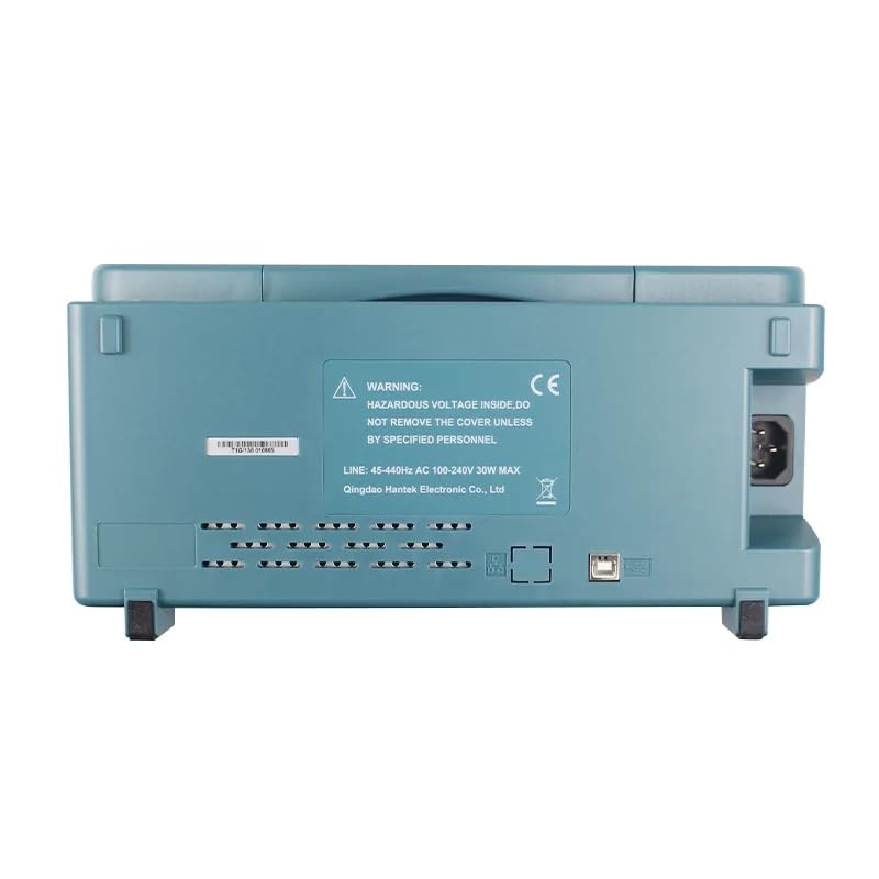
Figure 3.3: Rear view of the oscilloscope, highlighting power input and warning labels.
4. Setup
Follow these steps for initial setup of your oscilloscope:
- Unboxing: Carefully remove the oscilloscope and all accessories from the packaging. Inspect for any signs of damage.
- Power Connection: Connect the power cable to the oscilloscope's power input on the rear panel and then to a grounded AC power outlet.
- Probe Connection: Connect the desired probes to the BNC input channels on the front panel. Ensure a secure connection.
- Initial Power-On: Press the power button located on the front panel to turn on the device. The display will show the Hantek logo during startup.
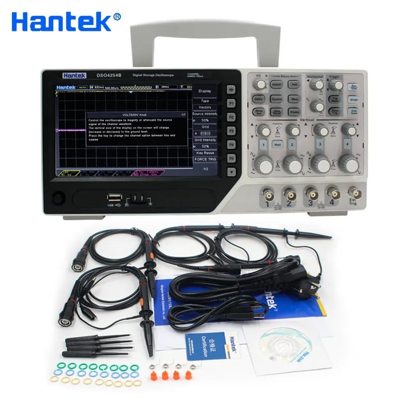
Figure 4.1: Oscilloscope and its standard accessories, including probes and power cable.
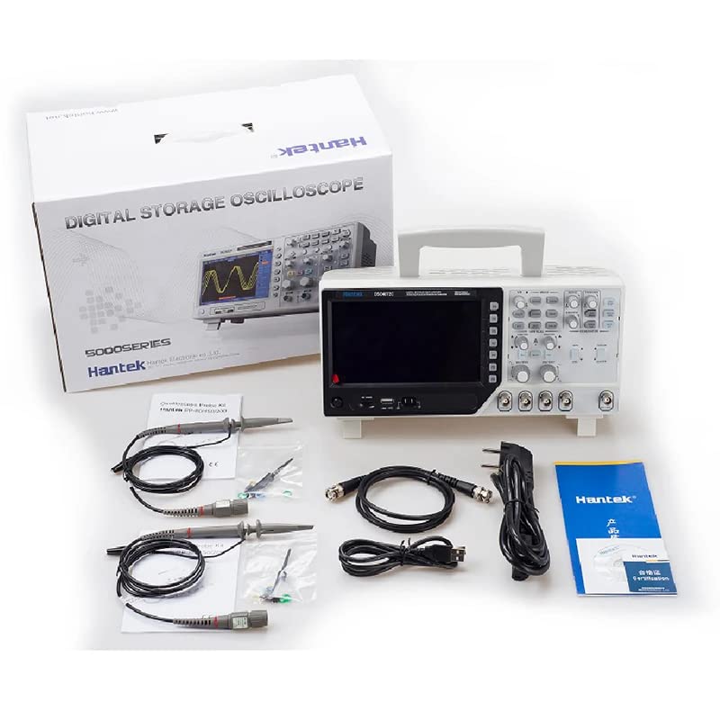
Figure 4.2: Contents of the product packaging, showing the oscilloscope and various cables.
5. Operating Instructions
This section details the basic operation of your GuliTech DOS4000B Series Oscilloscope.
5.1 Powering On and Initial Display
After connecting the power, press the power button. The oscilloscope will boot up, displaying the Hantek logo. Once fully initialized, Channel 1 (CH1) will typically be turned on by default, showing a horizontal line on the grid.
5.2 Adjusting Voltage and Position
The knobs beside each channel input (CH1, CH2, CH3, CH4) are used to adjust the voltage per division (vertical sensitivity) for that specific channel. The button above these knobs is for adjusting the vertical position of the waveform on the screen.
5.3 Using Multiple Channels
The DOS4000B series supports up to 4 channels simultaneously. You can enable or disable channels by pressing their respective buttons (e.g., CH1, CH2). Each channel's voltage and position can be adjusted independently.
5.4 Auto-Set Function
Pressing the 'AUTO' button automatically adjusts the oscilloscope settings (vertical, horizontal, and trigger) to display a stable waveform. For example, when measuring a DC 5V signal, the auto-set function might configure the display to 2V per meter.
5.5 Measurement Functions
Press the 'Meas' button to display various measurement results on the screen. This includes parameters like Vpp (peak-to-peak voltage), Vmax, Vmin, frequency, and more. You can toggle this display on or off as needed.
5.6 Coupling (DC/AC)
The coupling setting determines how the signal is connected to the oscilloscope's input. 'DC' coupling allows both AC and DC components of the signal to pass through. 'AC' coupling blocks the DC component, allowing only the AC component to be displayed. This is useful for observing small AC signals riding on a large DC offset.
5.7 Bandwidth Limit
The oscilloscope features a 20MHz bandwidth limit option for each channel. When enabled, this filter removes high-frequency noise and signals above 20MHz, providing a cleaner view of lower-frequency waveforms. This is particularly useful for observing power supply ripple.
Video 5.1: Demonstration of basic oscilloscope functions, including power-on, channel adjustment, auto-set, measurement display, and coupling settings.
This video illustrates how to connect a USB line to the oscilloscope via a BNC connector, power on the device, adjust voltage and position for individual channels, enable multiple channels, use the auto-set feature to display a DC 5V signal, and demonstrate AC coupling to observe power supply ripple. It highlights the practical application of various controls and settings.
6. Maintenance
Proper maintenance ensures the longevity and accuracy of your oscilloscope:
- Cleaning: Use a soft, damp cloth to clean the exterior of the instrument. Do not use abrasive cleaners or solvents.
- Storage: Store the oscilloscope in a cool, dry place when not in use. Protect it from dust and extreme temperatures.
- Calibration: Periodic calibration by qualified technicians is recommended to maintain measurement accuracy.
7. Troubleshooting
If you encounter issues with your oscilloscope, refer to the following common problems and solutions:
- No Display: Check power connections and ensure the power button is pressed. Verify the power outlet is functional.
- No Signal on Screen: Ensure probes are correctly connected to both the input and the circuit under test. Check channel enable buttons and adjust vertical/horizontal scales. Verify trigger settings.
- Unstable Waveform: Adjust the trigger level and mode. Ensure the signal is within the oscilloscope's input range.
- Incorrect Measurements: Verify probe attenuation settings (1X, 10X) match the oscilloscope's input settings. Check coupling (AC/DC) and bandwidth limit settings.
For persistent issues, contact GuliTech customer support or a qualified service center.
8. Specifications
Below are the detailed specifications for the GuliTech DOS4000B Series Oscilloscopes:
8.1 Model Selection Table

Figure 8.1: DSO4004 Series Model Selection Table.
8.2 General Specifications
| Feature | Specification |
|---|---|
| Product Dimensions | 8.66 x 5.91 x 4.72 inches |
| Item Weight | 1.1 Pounds |
| Item Model Number | G-DSO4084B |
| Batteries | 1 Lithium Ion batteries required (included) |
| Manufacturer | Hantek |
| Country of Origin | China |
8.3 Detailed Technical Specifications

Figure 8.2: Detailed Technical Specifications.
9. Warranty and Support
GuliTech provides a standard warranty for this product. For detailed warranty terms, please refer to the warranty card included with your purchase or contact GuliTech customer support. For technical assistance, troubleshooting, or service requests, please visit our official website or contact our support team.
Note: Product specifications and features are subject to change without prior notice.