1. Introduction
Thank you for choosing the Victor/RuoShui 606E Digital Current Clamp Meter. This device is a portable, professional measuring instrument designed for electrical testing. It features auto-ranging capabilities, a 3 3/4 digit display, and measures AC/DC voltage, AC current, resistance, capacitance, diode, frequency, and temperature. This manual provides essential information for safe and effective operation.
Safety Information
Always adhere to safety precautions to prevent electric shock or damage to the meter. Read all safety information before using the product.
- Do not exceed the maximum input values specified for each measurement range.
- Ensure the test leads are properly connected and the function switch is set to the correct range before making measurements.
- Do not use the meter if it appears damaged or if the battery cover is not properly closed.
- Exercise extreme caution when working with voltages above 60V DC or 30V AC RMS, as these pose a shock hazard.
2. Product Overview
The Victor/RuoShui 606E is a versatile clamp meter designed for various electrical measurements. It combines the functionality of a digital multimeter with a current clamp, allowing for non-invasive current measurements.
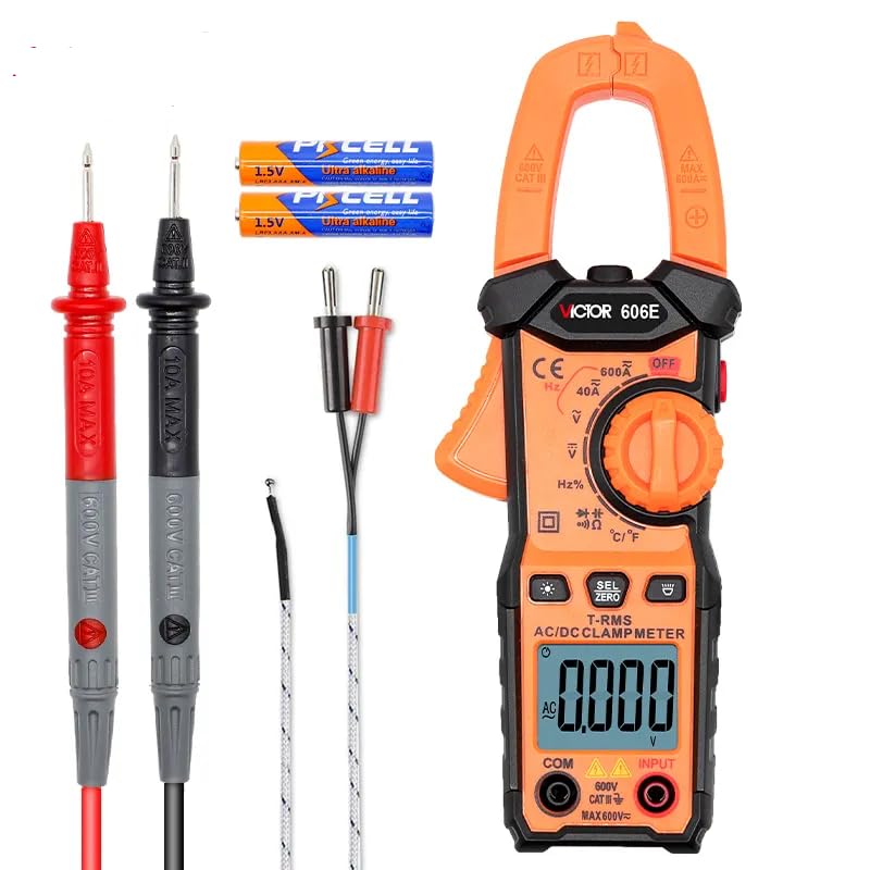
Figure 2.1: Victor/RuoShui 606E Clamp Meter and included accessories.
Key Features
- Auto Range: Automatically selects the appropriate measurement range.
- True RMS: Provides accurate measurements for non-sinusoidal waveforms.
- NCV (Non-Contact Voltage): Detects AC voltage without direct contact.
- Flashlight & Backlight: Enhances visibility in dimly lit environments.
- Data Hold: Freezes the displayed measurement for easy reading.
- Automatic Shut-down: Conserves battery life.

Figure 2.2: Overview of the 606E's comprehensive features.
3. Setup
3.1 Battery Installation
The Victor/RuoShui 606E requires 2 x 1.5V AAA batteries for operation. Follow these steps to install or replace the batteries:
- Ensure the meter is powered off and disconnect all test leads from the input terminals.
- Locate the battery compartment cover on the back of the meter.
- Use a screwdriver to loosen the screw securing the battery cover.
- Remove the cover and insert the 2 x 1.5V AAA batteries, observing the correct polarity (+/-) as indicated inside the compartment.
- Replace the battery cover and tighten the screw securely.

Figure 3.1: Battery compartment with warning label. Always remove test leads before opening.
3.2 Test Lead Connection
For voltage, resistance, capacitance, diode, and frequency measurements, connect the test leads as follows:
- Insert the red test lead into the 'VΩHz' input terminal.
- Insert the black test lead into the 'COM' (common) input terminal.
For temperature measurements, connect the temperature probe to the 'VΩHz' and 'COM' terminals, observing polarity if applicable to the probe type.
4. Operating Instructions
4.1 Power On/Off
To power on the meter, rotate the function switch from the 'OFF' position to any desired measurement function. To power off, rotate the function switch back to 'OFF'. The meter also features an automatic shut-down function to conserve battery life after a period of inactivity.
4.2 Function Selection
The rotary switch allows you to select different measurement functions. The meter will automatically select the appropriate range within the chosen function.

Figure 4.1: The large HD LCD display and function selection dial.
4.3 AC Current Measurement (Clamp)
To measure AC current:
- Rotate the function switch to the 'A~' position.
- Press the jaw release lever to open the clamp jaw.
- Encircle a single conductor with the clamp jaw. Ensure the jaw is fully closed.
- Read the AC current value on the display.

Figure 4.2: Measuring AC current with the clamp jaw.
4.4 Voltage, Resistance, Capacitance, Diode, Frequency, Temperature Measurement
For these measurements, ensure test leads are connected as described in Section 3.2.
- Voltage (AC/DC): Rotate the switch to 'V~' or 'V=' and connect test leads in parallel to the circuit.
- Resistance (Ω): Rotate the switch to 'Ω' and connect test leads across the component.
- Capacitance (F): Rotate the switch to 'F' and connect test leads across the capacitor.
- Diode Test: Rotate the switch to 'Diode' symbol and connect test leads across the diode.
- Frequency (Hz): Rotate the switch to 'Hz' and connect test leads to the signal source.
- Temperature (°C/°F): Rotate the switch to '°C/°F' and connect the temperature probe.
4.5 Special Functions
- NCV (Non-Contact Voltage): Press the 'NCV' button. Bring the top of the meter near an AC voltage source. The meter will indicate voltage presence with an audible alarm and visual indicator.
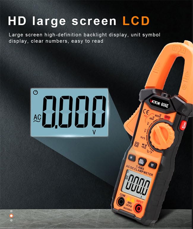
Figure 4.3: NCV non-contact voltage detection in action.
- Flashlight: Press the flashlight button to turn on/off the built-in flashlight for illuminating the measurement area.
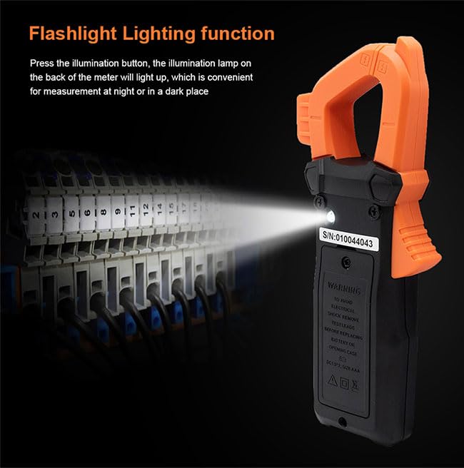
Figure 4.4: Using the flashlight function in a dark environment.
- Data Hold: Press the 'HOLD' button to freeze the current reading on the display. Press again to release.
- Backlight: Press the backlight button to turn on/off the display backlight.
5. Maintenance
5.1 Cleaning
Wipe the meter's casing with a damp cloth and mild detergent. Do not use abrasives or solvents. Ensure the meter is completely dry before use.
5.2 Battery Replacement
Refer to Section 3.1 for detailed instructions on battery replacement. Replace batteries promptly when the low battery indicator appears on the display to ensure accurate measurements.
5.3 Storage
If the meter is not used for an extended period, remove the batteries to prevent leakage and damage. Store the meter in a cool, dry place, away from direct sunlight and extreme temperatures.
6. Troubleshooting
| Problem | Possible Cause | Solution |
|---|---|---|
| Meter does not power on. | Dead or incorrectly installed batteries. | Check battery polarity or replace batteries. |
| Inaccurate readings. | Incorrect function selected, poor test lead connection, or external interference. | Verify function switch position, ensure secure test lead connection, move away from strong electromagnetic fields. |
| Display shows 'OL' (Overload). | Input value exceeds the selected range. | Select a higher range or ensure the measurement is within the meter's capabilities. |
| NCV function not working. | No AC voltage present or meter not close enough to the source. | Ensure AC voltage is present and bring the NCV sensor closer to the conductor. |
7. Specifications
The following table outlines the technical specifications for the Victor/RuoShui 606E Digital Current Clamp Meter.

Figure 7.1: Detailed technical specifications for the 606E model.
- Safety Compliance: CE certification, Meets IEC61010-1, IEC61010-2-032, IEC 61010-031, IEC61010 CAT.III 600V.
- Display: 4000 counts, large screen high-definition backlight display.
- Sampling Rate: Approximately 3 times per second.
- Power: 2 x 1.5V AAA batteries.
- Product Dimensions: 200 x 75 x 35 mm (approx. 8.66 x 5.91 x 4.72 inches).
- Product Weight: 150g (approx. 0.5 Kilograms).
8. Warranty and Support
The Victor/RuoShui 606E Digital Current Clamp Meter is manufactured to high-quality standards. For specific warranty details, please refer to the warranty card included with your product or contact the retailer where the product was purchased.
For technical support or inquiries, please visit the official GuliTech store on Amazon: GuliTech Store.