Introduction
This user manual provides detailed instructions for the operation and maintenance of the GuliTech Victor/RuoShui 4106A Earth Resistance Tester. This device is designed for precise earth resistance and soil resistivity measurements, featuring 3-pole and 4-pole methods, AC True RMS voltage measurement, and a large LCD display with backlight for clear readings. Please read this manual thoroughly before use to ensure safe and effective operation.
Safety Information
Always adhere to the following safety precautions to prevent injury or damage to the instrument:
- Do not operate the tester if the battery compartment is open or if the battery door is not securely closed.
- Before opening the case or battery door, always remove all test leads from the instrument.
- Ensure the instrument is used within its specified operating temperature and humidity ranges.
- Avoid exposing the device to excessive vibration or shock.
- Do not attempt to repair or modify the instrument yourself. Refer all servicing to qualified personnel.
- Observe all local and national safety codes.

Figure 1: Back view of the tester, highlighting the battery compartment and a warning label indicating to remove test leads before opening and not to operate with the battery door open.
Package Contents
Verify that all items listed below are included in your package:
- Victor 4106A Earth Resistance Tester
- Soft Carrying Bag
- Hand Rope
- User's Manual
- Auxiliary Earth Spikes (2 pieces)
- Testing Wires: 5m (black), 5m (green), 15m (red), 10m (yellow)
- 8 x 1.5V LR6 (AA) Alkaline Batteries (pre-installed or included separately)
- Power Adapter (15V)
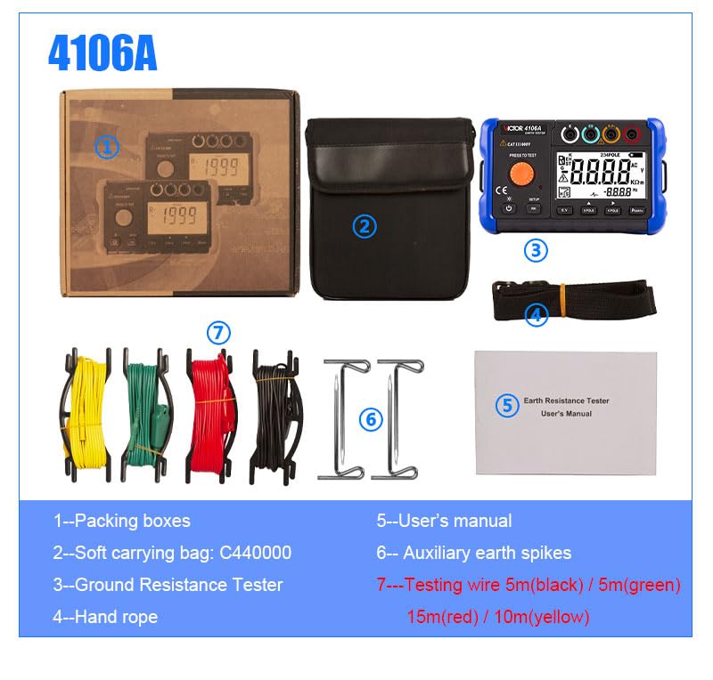
Figure 2: Overview of the package contents for the Victor 4106A Earth Resistance Tester.
Product Overview
The Victor 4106A is a professional digital earth resistance tester designed for accurate and reliable measurements. It features a large LCD display with white LED backlight for easy readability in various conditions.

Figure 3: Front view of the Victor 4106A Earth Resistance Tester.

Figure 4: Labeled diagram of the Victor 4106A components.
- Rope hanging hole
- Measuring knob
- E terminal - black
- ES terminal - green
- S terminal (P terminal) - red
- H terminals (C terminals) - blue
- Display screen
- Data save/delete key
- Power adapter interface
- 4 pole method/shift right button
- 3 pole method button
- Voltage measurement function (E.V) button
- RK function/Setting function button
- Power/Backlight button
Setup
Battery Installation
The Victor 4106A is powered by 8 x 1.5V LR6 (AA) alkaline batteries or a 15V power adapter.
- Ensure the device is turned off and all test leads are disconnected.
- Locate the battery compartment on the back of the unit.
- Rotate the locking mechanism to open the battery cover.
- Insert 8 AA alkaline batteries, observing the correct polarity (+/-) as indicated inside the compartment.
- Close the battery cover and secure the locking mechanism.

Figure 5: Detail showing the battery compartment and power adapter outlet.
Connecting Test Leads and Earth Spikes
Refer to Figure 4 for terminal locations. Connect the test leads to the corresponding terminals (E, ES, S, H) and the auxiliary earth spikes as required for your measurement method.
Operating Instructions
Power On/Off and Backlight
Press the Power/Backlight button (14) to turn the unit on or off. A short press of the same button will toggle the white LED backlight.
Earth Resistance Measurement (RE)
The tester supports both 3-pole and 4-pole methods for earth resistance measurement.
- 3-Pole Method: Press the 3 POLE button (11). Connect the test leads and auxiliary earth spikes according to the diagram in the full user manual.
- 4-Pole Method: Press the 4 POLE button (10). Connect the test leads and auxiliary earth spikes according to the diagram in the full user manual. This method provides higher accuracy by eliminating the resistance of the test leads.
After setting up, press the large orange PRESS TO TEST button (2) to initiate the measurement. The result will be displayed on the screen (7). The device features automatic range detection.
Soil Resistivity Measurement (ρ)
To measure soil resistivity, press the ρEARTH button. This measurement requires setting the interval of auxiliary earth rods (1.0 m ~ 30.0 m). Refer to the full user manual for detailed setup and calculation procedures.
AC True RMS Voltage Measurement (E.V)
Press the E.V button (12) to enter AC voltage measurement mode. The tester can measure AC voltage in the range of 0~50V with a bandwidth of 40Hz ~ 200Hz.
RK Resistance Test
The RK resistance test function (button 13) allows for the removal of line resistance effects from measurements. Consult the detailed manual for specific application instructions.
Earth Comparison Test
This function allows you to evaluate measurement results against a preset "pass/fail" limit. The device will provide audio alarms accordingly. Use the RK/SETUP button (13) to access setup options for this feature.
Automatic Shutdown
The automatic shutdown time can be set from 0 to 90 minutes to conserve battery life. This setting can typically be adjusted via the SETUP function (button 13).
Maintenance
Cleaning
Wipe the instrument with a soft, damp cloth. Do not use abrasive cleaners or solvents. Ensure the device is dry before storage or next use.
Storage
When not in use for extended periods, remove the batteries to prevent leakage. Store the device in its soft carrying bag in a cool, dry place, away from direct sunlight and extreme temperatures.
Troubleshooting
If you encounter issues with your Victor 4106A, consider the following common solutions:
- No Power: Check battery installation and ensure batteries are not depleted. Try using the 15V power adapter.
- Inaccurate Readings: Ensure test leads are securely connected and not damaged. Verify that auxiliary earth spikes are properly inserted into the ground. Check for external electrical interference.
- Display Issues: If the display is dim, activate the backlight. If the display shows "OL" (Over-range), the measured value exceeds the selected range.
- Device Not Responding: Try turning the device off and on again. If the issue persists, remove and reinsert batteries.
For persistent problems, contact customer support or refer to the comprehensive troubleshooting section in the full user manual.
Specifications
| Feature | Specification |
|---|---|
| Earth Resistance Measurement (RE) |
|
| Soil Resistivity Measurement (ρ) |
|
| AC True RMS Voltage (E.V) |
|
| Display | Large LCD with white LED backlight, 2000 counts |
| Power Supply | 8 x 1.5V LR6 (AA) alkaline batteries or 15V power adapter |
| Automatic Shutdown | Adjustable from 0 ~ 90 minutes |
| Operating Temperature & Humidity | 0 ~ 40°C, relative humidity ≤ 85% |
| Storage Temperature & Humidity | -20 ~ 60°C, relative humidity ≤ 90% |
| Dimensions (L x W x H) | 178 × 110 × 59 mm |
| Weight | Approx. 600g (including batteries) |
| Calibration Period | One year |
| Warm-up Time | 10 minutes after power on |
| Safety Compliance | CAT III 600V, EMC, ISO 9001, RoHS |

Figure 6: Comprehensive specifications table for the Victor 4106A.
Warranty and Support
The accuracy of this instrument is ensured with a recommended calibration period of one year. For warranty claims, technical support, or service inquiries, please contact your authorized GuliTech dealer or customer service. Please retain your proof of purchase for warranty validation.
For further assistance, please visit the official GuliTech website or contact their customer support channels.