1. Product Overview
This manual provides instructions for the SPJIUQI 6-Terminal Ignition Key Switch, designed for specific heavy equipment applications. It functions as a replacement part for the ignition system.

Figure 1: SPJIUQI 6-Terminal Ignition Key Switch and accompanying keys.
2. Compatibility
This ignition key switch is compatible with the following equipment models:
Mitsubishi Caterpillar Forklift Truck:
- Compatible with Mitsubishi Caterpillar Forklift Truck models requiring part numbers 91204-17400, 91205-14900, 91106-07400, GC25K-AT82C.
Mitsubishi Tractors:
- D-Series: D1300, D1500, D1650, D1800, D1850, D2000, D2300, D2350, D2500, D2650
- MT-Series: MT17, MT17D, MT18, MT18D, MT20D, MT21, MT21D, MT22, MT22D, MT23, MT23D, MT25, MT25D, MT26, MT26D, MT27, MT27D, MT30, MT30D, MT33, MT33D, MT160, MT160D, MT180, MT180D, MT185, MT205, MT210, MT210D, MT245, MT250, MT250D, MT300, MT300D, MT372, MT470, MT750, MT1401, MT1601, MT1801, MT2001, MT2201, MT2501, MTX225
- S-Series: S370, S373D
Satoh Tractors:
- S373D Beaver, S470, S630D, S750, ST1820, ST1840, ST2020, ST2320, ST2340
3. What's in the Box
The product package includes:
- One (1) Ignition Key Switch
- Two (2) Keys
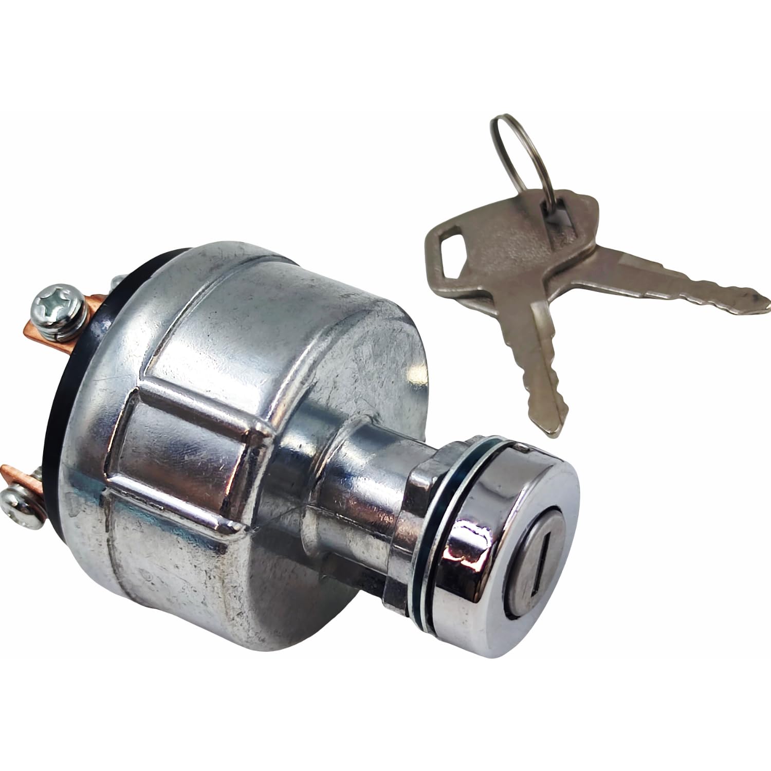
Figure 2: Ignition switch and keys as received.
4. Setup and Installation
Installation of the ignition key switch requires careful attention to wiring connections. It is recommended that installation be performed by a qualified technician.
Wiring Diagram and Terminal Identification:
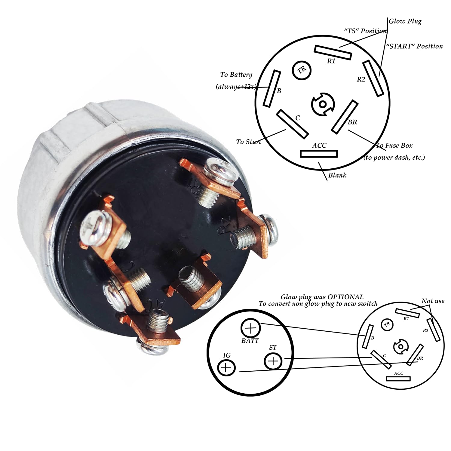
Figure 3: Detailed wiring diagram for the 6-terminal ignition switch. This diagram illustrates the connection points for battery, start, accessory, and glow plug circuits.
The switch features 6 terminals. Refer to the wiring diagram (Figure 3) for correct connections. The terminals are typically labeled or correspond to specific functions:
- B (Battery): Connects to the main battery positive terminal (always +12V).
- C (Start): Connects to the starter solenoid.
- ACC (Accessory): Connects to accessory circuits (e.g., radio, lights, dash power).
- TR / R1 / R2 (Glow Plug / Run): These terminals may be used for glow plug circuits or other run-position accessories, depending on the specific vehicle's wiring. The diagram indicates "Glow Plug" and "START" positions.
- BR (Fuse Box): Connects to the fuse box for power distribution to various dash components.
Important: Ensure all connections are secure and correctly matched to the vehicle's wiring harness. Incorrect wiring can lead to electrical system damage or malfunction.

Figure 4: Rear view of the ignition switch, highlighting the 6 screw terminals for wiring connections.
5. Operating Instructions
The ignition key switch operates with an OFF-ON-IGNITION sequence. Insert the key into the switch and turn it to the desired position:
- OFF: The engine is off, and all electrical systems are de-energized (except for constant battery connections). The key can be removed in this position.
- ON (ACC/Run): Turning the key to this position energizes the accessory and ignition circuits, allowing the vehicle's electrical systems to operate without starting the engine.
- IGNITION (Start): This is a momentary position. Turning the key fully to this position engages the starter motor to crank the engine. Release the key once the engine starts; it will spring back to the "ON" position.

Figure 5: Ignition switch with a key inserted, ready for operation.
6. Maintenance
The SPJIUQI Ignition Key Switch is designed for durability and typically requires minimal maintenance. However, regular checks can help ensure its longevity and proper function:
- Connection Integrity: Periodically inspect the wiring connections at the terminals for tightness and corrosion. Loose or corroded connections can lead to intermittent operation or electrical issues.
- Key Condition: Ensure the keys are not bent or damaged, as this can affect the smooth operation of the lock cylinder.
- Environmental Protection: While designed for industrial use, protect the switch from excessive moisture, dirt, and debris to prevent internal damage.
7. Troubleshooting
If you experience issues with the ignition key switch, consider the following troubleshooting steps:
- No Power in ON/ACC Position:
- Check the main battery connection to the 'B' terminal.
- Inspect fuses related to the accessory and ignition circuits.
- Verify the wiring to the 'ACC' and 'BR' terminals.
- Engine Does Not Crank:
- Ensure the battery is charged and connections are secure.
- Check the wiring from the 'C' (Start) terminal to the starter solenoid.
- Confirm the starter motor itself is functional.
- Key Sticks or Is Difficult to Turn:
- Apply a small amount of graphite lubricant to the keyhole. Avoid oil-based lubricants as they can attract dirt.
- Inspect the key for damage or bending.
- Intermittent Operation:
- Check all terminal connections for looseness or corrosion.
- Inspect the wiring harness for any damage or frayed wires.
If problems persist after troubleshooting, consult a qualified mechanic or electrical technician.
8. Specifications
| Feature | Detail |
|---|---|
| Part Numbers | 91204-17400, 91205-14900, 91106-07400, GC25K-AT82C |
| Brand | SPJIUQI |
| Operation Mode | OFF-ON-IGNITION |
| Current Rating | 5 Amps |
| Operating Voltage | 12 Volts |
| Contact Type | Normally Open |
| Connector Type | Plug In |
| Terminal Type | Screw (6-terminal) |
| Circuit Type | 6-way |
| Actuator Type | Ignition |
| Product Dimensions (L x W x H) | 3.9 x 2.6 x 2.6 inches |
| Item Weight | 9.7 ounces |

Figure 6: Top dimension measurement of the ignition switch.

Figure 7: Side dimension measurement of the ignition switch.
9. Warranty and Support
Specific warranty information for this product is not provided in the available documentation. For warranty details or technical support, please contact the seller or manufacturer directly through their official channels.


