
238877
Instruction Manual
238877 Motor Feed Replacement Control Board
For Hobart Handler 140 (12-pin Connector)
1. Introduction
This manual provides essential information for the proper installation, operation, and maintenance of the 238877 Motor Feed Replacement Control Board. This board is designed as a direct replacement for the original control board in the Hobart Handler 140 welding machine, specifically models utilizing a 12-pin connector for the motor feed.
Please read this manual thoroughly before attempting any installation or service to ensure safety and optimal performance of the replacement part.
2. Compatibility
This replacement control board is compatible with:
- Hobart Handler 140 welding machines.
- Systems requiring a 12-pin connector for the motor feed control board.
Verify your existing control board's connector type and part number (238877) before proceeding with installation to ensure proper fit and function.
3. Safety Information
Always prioritize safety when working with electrical components and welding equipment. Failure to follow these safety guidelines may result in serious injury or damage to equipment.
- DANGER: Always disconnect the welding machine from the main power supply before attempting any installation, maintenance, or repair.
- Ensure the work area is dry and well-ventilated.
- Wear appropriate personal protective equipment (PPE), including safety glasses and gloves.
- If you are not confident in your ability to perform the installation, seek assistance from a qualified technician.
- Do not touch live electrical parts.
- Inspect all wiring and connections for damage before and after installation.
4. Setup & Installation
This section outlines the general steps for replacing the motor feed control board. Specific disassembly and reassembly procedures for your Hobart Handler 140 may vary; refer to your welder's original service manual for detailed instructions.
Tools Required:
- Screwdriver set (Phillips and/or Flathead, as needed)
- Needle-nose pliers (optional, for tight connectors)
Installation Steps:
- Disconnect Power: Ensure the Hobart Handler 140 is completely unplugged from the electrical outlet.
- Access Control Board: Carefully open the welding machine's casing to gain access to the existing motor feed control board. This typically involves removing screws and panels.
- Document Connections: Before disconnecting anything, take clear photos or make a diagram of all wire connections to the old control board. Pay close attention to the orientation and pin assignments of the 12-pin connector and any other wires.
- Disconnect Old Board: Gently disconnect all wires and connectors from the old control board. Remove any mounting screws or clips securing the old board in place.
- Remove Old Board: Carefully lift and remove the old control board from the welding machine.
- Install New Board: Position the new 238877 Motor Feed Replacement Control Board in the same location as the old one. Secure it with the original mounting screws or clips.
- Connect Wires: Using your photos or diagrams as a guide, carefully reconnect all wires and connectors to the new control board. Ensure the 12-pin connector is firmly seated.
- Inspect Connections: Double-check all connections to ensure they are secure and correctly oriented.
- Close Casing: Carefully reassemble the welding machine's casing, ensuring no wires are pinched.
- Test Functionality: Plug the welding machine back into the power supply and perform a functional test to ensure the motor feed operates correctly.

Figure 1: Overview of the 238877 Motor Feed Replacement Control Board, highlighting the 12-pin connector for easy identification during installation.

Figure 2: Angled view of the control board, illustrating the arrangement of key components such as heat sinks and relays, which are crucial for motor control.
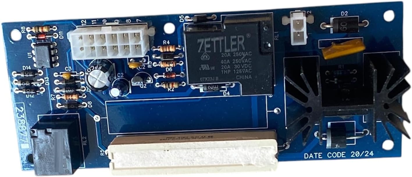
Figure 3: Alternative view of the control board, providing a different perspective on the component layout and overall board design.
5. Operation
The 238877 Motor Feed Replacement Control Board is an integral component of the Hobart Handler 140's wire feed system. Once correctly installed, it functions automatically as part of the welding machine's internal circuitry to regulate the speed and consistency of the wire feed.
No direct user interaction with the control board itself is required for operation. Its function is to ensure the welding wire is fed smoothly and at the correct rate as determined by the welder's settings.
6. Maintenance
The 238877 Motor Feed Replacement Control Board is designed for long-term reliability and requires minimal maintenance. However, adhering to general care practices for electronic components can extend its lifespan:
- Keep Clean: Periodically, when the welding machine is disconnected from power, inspect the board for dust, debris, or metal shavings. Use compressed air or a soft, dry brush to gently remove any accumulation.
- Avoid Moisture: Ensure the welding environment is dry. Moisture can cause short circuits and damage electronic components.
- Check Connections: During routine maintenance of your welder, verify that all connections to the control board remain secure and free from corrosion.
7. Troubleshooting
If you experience issues after installing the new control board, consider the following troubleshooting steps:
| Symptom | Possible Cause | Solution |
|---|---|---|
| Wire feed not working or inconsistent. | Incorrect or loose connections to the control board. | Disconnect power, open casing, and re-check all wire connections, especially the 12-pin connector. Ensure they are fully seated. |
| No power to the control board. | Main power supply issue or internal wiring problem. | Verify the welding machine is plugged in and receiving power. Check internal power supply connections to the board. |
| Board appears damaged or burnt. | Electrical surge or component failure. | Immediately disconnect power. The board may need replacement. Contact support. |
If troubleshooting steps do not resolve the issue, it is recommended to consult a qualified technician or contact the product support for further assistance.
8. Specifications
| Attribute | Detail |
|---|---|
| Model Number | 238877 |
| Part Number | 238877 |
| Compatibility | Hobart Handler 140 (12-pin Connector) |
| Item Weight | Approximately 1 pound (0.45 kg) |
| Product Dimensions | 9 x 5 x 2 inches (22.86 x 12.7 x 5.08 cm) |
| Manufacturer | Generic |
| Country of Origin | USA |
9. Warranty & Support
Warranty Information:
This 238877 Motor Feed Replacement Control Board comes with a 60-day replacement warranty from the date of purchase. This warranty covers defects in materials and workmanship under normal use. It does not cover damage resulting from improper installation, misuse, accidents, or unauthorized modifications.
Customer Support:
For technical assistance, warranty claims, or any questions regarding the 238877 Motor Feed Replacement Control Board, please contact the seller or manufacturer through the platform where the product was purchased. Provide your order details and a clear description of the issue for prompt support.
Ask a question about this manual
Ask about setup, troubleshooting, compatibility, parts, safety, or missing instructions. Manuals+ will review the question and use this page’s manual context to help answer it.