1. Introduction
The PerGar PICKit3 is a development tool designed for learning, evaluating, and developing Microchip PIC series Microcontroller Units (MCUs). It integrates both online simulation and downloading capabilities, making it a comprehensive solution for embedded systems development. This manual provides essential information for setting up, operating, and maintaining your PICKit3 programmer.
2. Product Overview
2.1 Included Components
- 1 x PICKIT3 Programmer Unit
- 1 x ICSP Connection Cable
- 1 x USB Cable

Image 2.1: The PICKit3 programmer unit, USB cable, and ICSP connection cable.
2.2 Key Features
- Wide Compatibility: Supports devices compatible with Microchip's official MPLAB Integrated Development Environment (IDE).
- Seamless Integration: Connects with PIC series MCUs via the ICSP (In-Circuit Serial Programming) interface.
- Versatile Development Tool: Offers both programming (burning/writing FLASH ROM) and simulation functions (full-speed running, single-step debugging, breakpoint debugging).
- Future-Proof Design: Firmware is upgradable to support new PIC models introduced by Microchip.
- Portable and User-Friendly: Compact and lightweight design for ease of use and transport.
2.3 Device Indicators and Ports
The PICKit3 unit features LED indicators for Power, Active, and Status, providing visual feedback on its operational state. It connects to a PC via a USB interface and to the target MCU board via a standard ICSP interface.
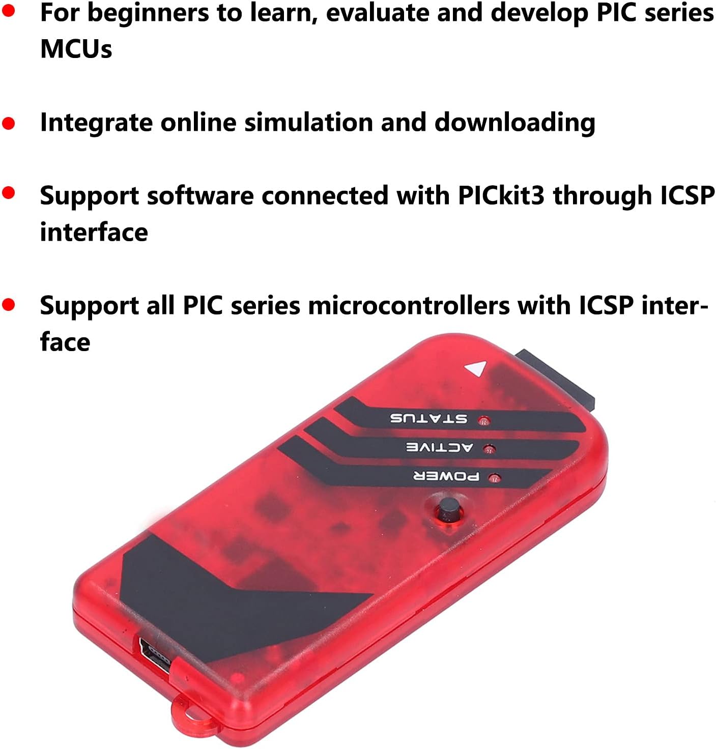
Image 2.2: The PICKit3 programmer displaying its Power, Active, and Status indicator LEDs.
3. Setup
3.1 Connecting to a PC
- Connect one end of the provided USB cable to the USB port on the PICKit3 programmer.
- Connect the other end of the USB cable to an available USB port on your computer.
- The PICKit3 development tool has a built-in driver for high-speed USB communication. Your operating system should automatically detect and install the necessary drivers.
3.2 Connecting to the Target Board
The PICKit3 connects to your target PIC microcontroller board using the ICSP standard interface. Ensure correct pin orientation to prevent damage to the programmer or the target device.
- Identify the ICSP header on your target PIC microcontroller board.
- Connect the ICSP connection cable to the ICSP port on the PICKit3 programmer.
- Carefully connect the other end of the ICSP cable to the ICSP header on your target board, ensuring that the pin assignments (VPP/MCLR, VDD, VSS, PGD, PGC) match correctly. Refer to your target board's documentation for specific ICSP pinouts.
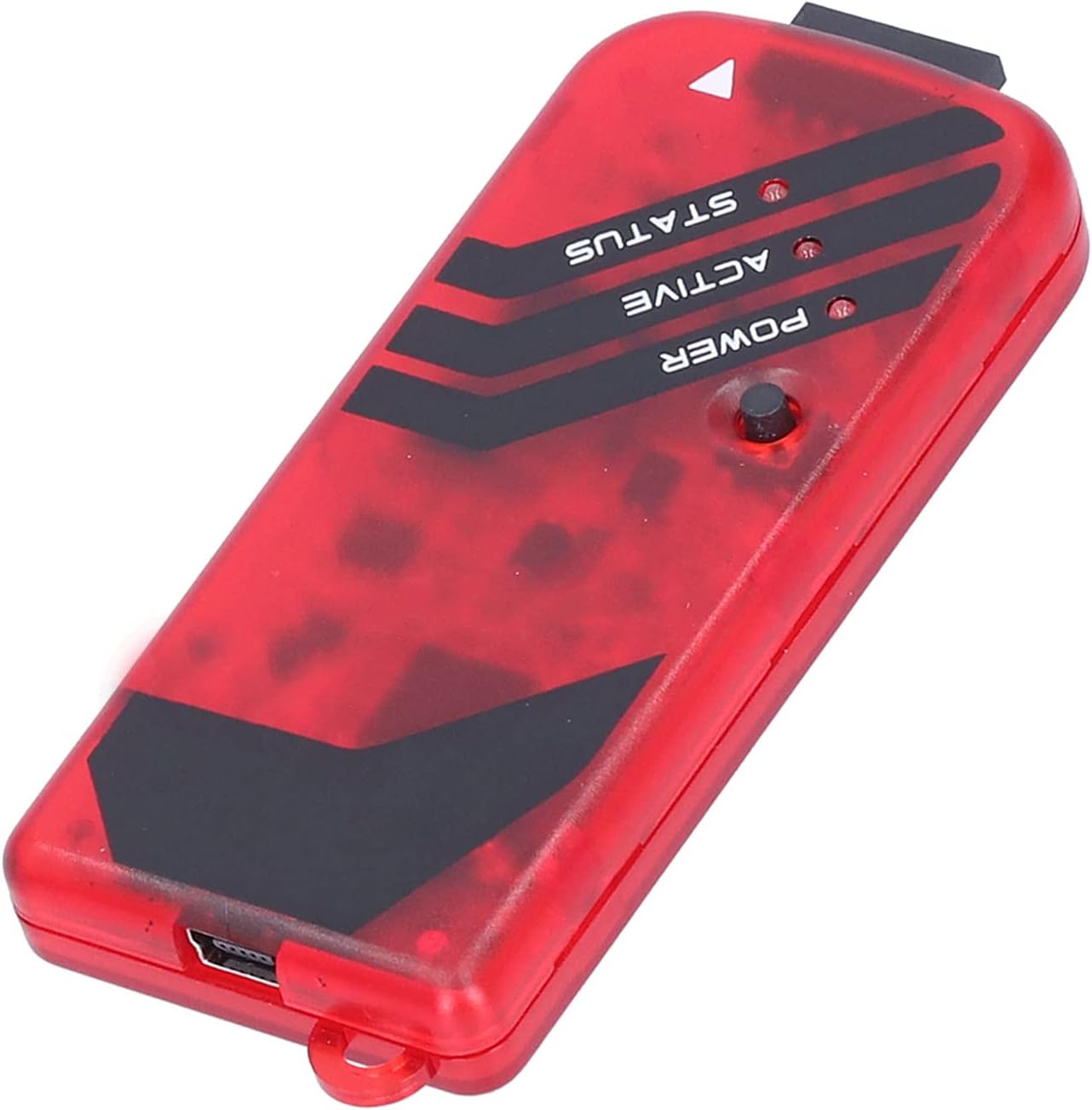
Image 3.1: The PICKit3 programmer with its USB and ICSP connection ports visible.
3.3 Software Installation
The PICKit3 directly supports devices within Microchip's official MPLAB Integrated Development Environment (IDE). Download and install the latest version of MPLAB IDE from the Microchip website (www.microchip.com/mplab/mplab-x-ide) to utilize the full functionality of the programmer.
4. Operating Instructions
4.1 Programming Function
The PICKit3 can burn and write FLASH ROM, EEPROM, and configuration bits to your PIC microcontroller. This process is typically managed through the MPLAB IDE.
- Ensure the PICKit3 is connected to both your PC and the target board.
- Open MPLAB IDE and load your project.
- Select the PICKit3 as your programmer/debugger tool within the MPLAB IDE settings.
- Use the 'Program' or 'Build and Program' function within MPLAB IDE to transfer your compiled code to the target PIC MCU.
4.2 Simulation and Debugging Function
The PICKit3 supports various debugging methods, including full-speed running, single-step debugging, and breakpoint debugging, all performed via the USB interface for fast response times.
- With the PICKit3 connected and selected in MPLAB IDE, switch to debug mode.
- Set breakpoints in your code where you want execution to pause.
- Start the debugger. You can step through your code line by line, observe variable values, and analyze program flow.
- Utilize the 'Run' function to execute code at full speed until a breakpoint is hit or the program completes.
4.3 Firmware Upgrade
Microchip periodically releases new PIC models and updates to the ICSP device support list. The PICKit3 firmware can be upgraded to support these new models. The upgrade process is typically automatic when connected to an internet-enabled PC running the latest MPLAB IDE, which will prompt you for firmware updates.
5. Maintenance
- Keep the PICKit3 programmer clean and free from dust. Use a soft, dry cloth for cleaning.
- Store the device in a cool, dry place away from direct sunlight and extreme temperatures.
- Avoid exposing the device to moisture or corrosive substances.
- Handle cables and connectors carefully to prevent damage.
6. Troubleshooting
6.1 Common Issues and Solutions
- Issue: PICKit3 not recognized by PC.
Solution: Ensure the USB cable is securely connected. Try a different USB port or cable. Verify that the necessary drivers are installed (usually automatic with MPLAB IDE). - Issue: Cannot connect to target device.
Solution: Check all ICSP connections for correct pinout and secure contact. Ensure the target board is powered correctly. Verify that the target PIC MCU is supported by the current PICKit3 firmware and MPLAB IDE version. - Issue: Programming/Debugging errors.
Solution: Confirm that the correct PIC microcontroller is selected in MPLAB IDE. Check for power supply issues on the target board. Ensure your code is compiled without errors. - Issue: Firmware upgrade failure.
Solution: Ensure a stable internet connection. Restart MPLAB IDE and try the upgrade again. Consult Microchip's support resources for specific error codes.
7. Specifications
| Feature | Detail |
|---|---|
| Model | PICKIT3 (PerGar9a24yz60us) |
| Manufacturer | PerGar |
| Connectivity Technology | USB |
| CPU Manufacturer Support | Microchip (PIC series MCUs) |
| Programming Function | FLASH ROM, EEPROM, Configuration Bits |
| Simulation Function | Full-speed running, single-step, breakpoint debugging |
| Interface with Target Board | ICSP Standard Interface |
| Firmware | Upgradable |
| Package Dimensions | 5.91 x 3.94 x 1.18 inches |
8. Warranty and Support
For warranty information and technical support, please refer to the official PerGar product page or contact PerGar customer service directly. Keep your purchase receipt for warranty claims.