1. Introduction
The Abestop AT312G is a versatile 3-in-1 handheld device integrating a digital oscilloscope, a digital multimeter, and a signal generator. Designed for various electrical testing and measurement applications, it offers portability and multiple functionalities for hobbyists, DIY enthusiasts, and professionals in fields such as appliance repair, automotive maintenance, and experimental teaching.
Key Features:
- 3-in-1 Functionality: Combines a 12 MHz bandwidth oscilloscope, a 6000-count digital multimeter, and a waveform generator.
- Compact and Portable: Lightweight design with a 240x320 color screen and integrated battery for convenient use on the go.
- Waveform Generator: Outputs sine, triangle, and square waves with adjustable frequency, duty cycle, and voltage parameters.
- Automatic Measurement: Features Vp-p, Vavg, Vrms, and Hz auto-measurement functions.
- Data Storage: Capable of storing 100 sets of data and 10 waveforms for later analysis.
- User-Friendly Interface: Includes automatic/manual switching and real-time data display.
2. Product Overview
This section provides an overview of the Abestop AT312G's physical components and controls.

Figure 2.1: Abestop AT312G device with included test leads, carrying case, and USB cable.

Figure 2.2: Front panel and port description of the Abestop AT312G.
2.1 Controls and Ports
- Charging Indicator Light: Located at the top, indicates charging status.
- Charging Interface: USB port for device charging.
- Multi-Function Buttons (F1-F4): Context-sensitive buttons for various settings and selections.
- AUTO Button: Used for auto-ranging in multimeter mode, auto-scaling in oscilloscope mode, and turning signal generator output on/off. Long-press to switch between DMM and Oscilloscope modes.
- Red Brightness/Signal Generator Button: Short press for backlight brightness, long press to activate the signal generator.
- SAVE Button: Used to save measurement data or waveforms.
- Functional Range Knob: Central rotary dial to select measurement functions (Voltage, Current, Resistance, Capacitance, Frequency, Diode, Oscilloscope, OFF).
- 10A Current Input Terminal: For high current measurements (up to 10A).
- Signal Output/Current Input Terminal (Out mA): Used for signal generator output and low current measurements (up to 600mA).
- COM Input: Common ground terminal for all measurements.
- Oscillographic/Voltage/Resistance/Current Input Port (VΩCX): Main input for voltage, resistance, capacitance, frequency, diode, and oscilloscope measurements.
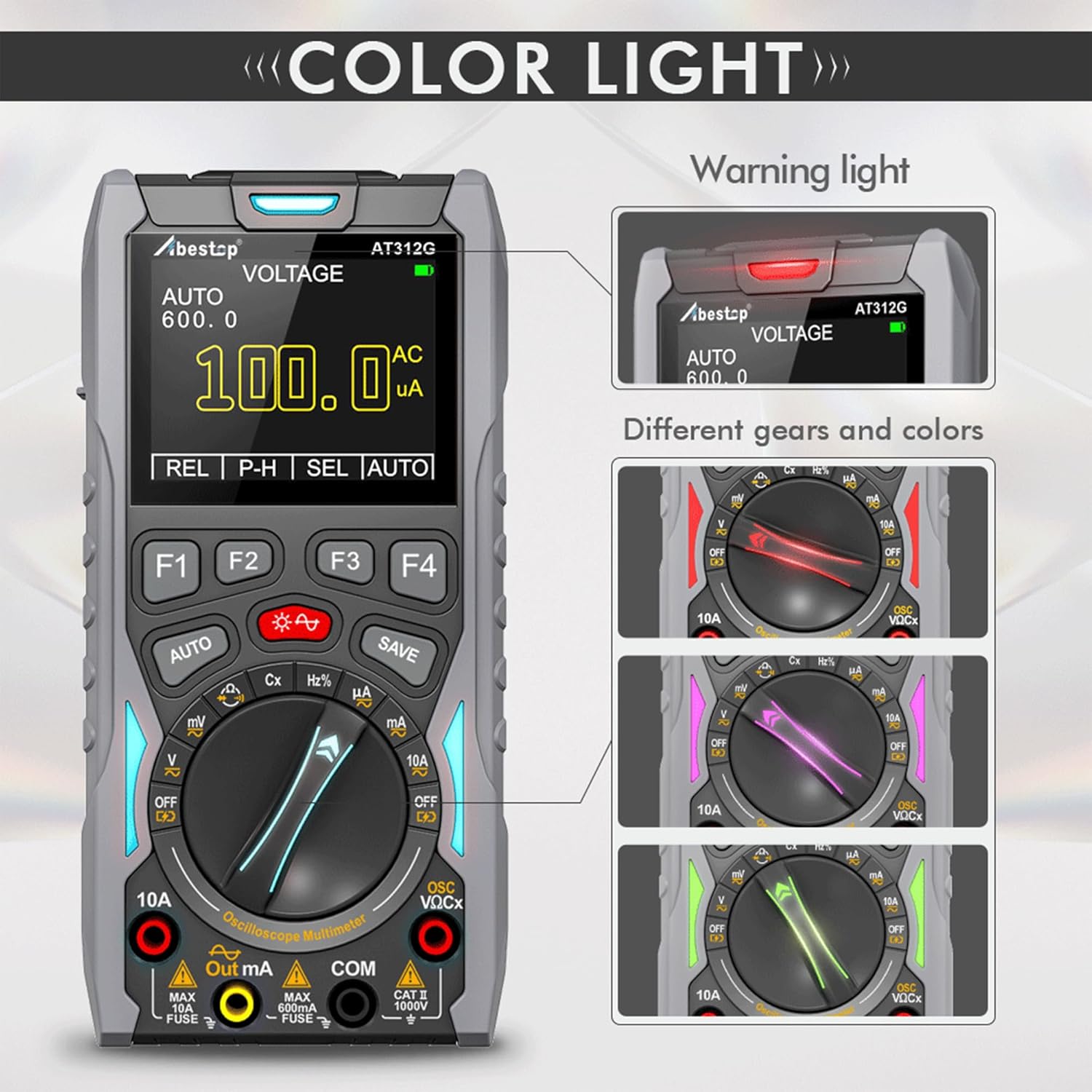
Figure 2.3: The device features color-coded warning lights that change based on the selected function, enhancing safety and usability.

Figure 2.4: Additional features include a soft rubber sheath for protection, an audible beep alarm, and an integrated kickstand for hands-free operation.
3. Setup
3.1 Initial Charging
Before first use, ensure the device is fully charged. Connect the provided USB cable to the charging interface on the device and to a suitable USB power adapter. The charging indicator light will show the charging status.
3.2 Connecting Test Leads
For most measurements, connect the red test lead to the VΩCX input and the black test lead to the COM input. For current measurements, refer to the specific instructions in the operating section.
4. Operating Instructions
The Abestop AT312G offers three primary modes of operation: Multimeter, Oscilloscope, and Signal Generator.
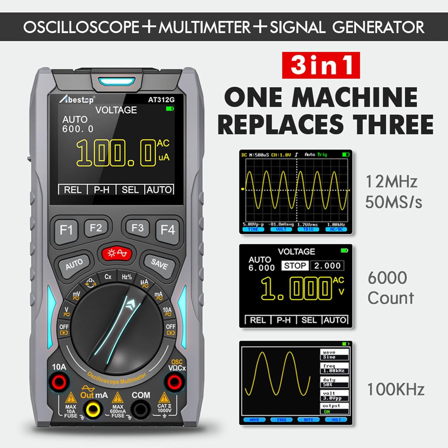
Figure 4.1: The 3-in-1 functionality of the Abestop AT312G, showing examples of oscilloscope waveforms, multimeter readings, and signal generator settings.
4.1 Multimeter Mode
To use the device as a multimeter, turn the functional range knob to the desired measurement function (e.g., V for Voltage, Ω for Resistance, A for Current, Cx for Capacitance, Hz for Frequency, Diode for Diode Test).
- Voltage Measurement (DC/AC): Select 'V'. Use the F3 button (labeled 'SEL') to switch between DC and AC voltage measurement. The device will auto-range, or you can manually adjust the range using F4 ('RNG').
- Current Measurement (DC/AC): Select 'A'. For high currents (up to 10A), connect the red lead to the 10A input. For low currents (up to 600mA), connect the red lead to the Out mA input. Use F3 ('SEL') to switch between DC and AC current.
- Resistance Measurement: Select 'Ω'.
- Capacitance Measurement: Select 'Cx'.
- Frequency Measurement: Select 'Hz'.
- Diode Test: Select 'Diode'.
- Continuity Test: Select 'Continuity' (often combined with resistance or diode function).
The 'AUTO' button can be pressed briefly to enable auto-ranging for most functions. The 'REL' (F1) button is for relative measurements, setting the current reading as a zero reference. The 'P-H' (F2) button activates peak hold mode, capturing maximum and minimum values.
4.2 Oscilloscope Mode
To enter oscilloscope mode, turn the functional range knob to 'OSC' or long-press the 'AUTO' button while in a multimeter voltage mode.
- Waveform Display: The screen will display the input waveform.
- Auto-Scaling: Briefly press the 'AUTO' button to automatically adjust the vertical scale and time base for optimal waveform display.
- Trigger Modes: The device supports automatic, conventional, and single-shot trigger modes for capturing stable waveforms.
- Waveform Hold: During measurement, you can hold the waveform on the screen.
4.3 Signal Generator Mode
The signal generator function allows you to output various waveforms for testing circuits.
- Activation: First, turn the functional range knob to 'V' (Voltage measuring mode). Then, long-press the red brightness/signal generator button. The device will start outputting a default 1 kHz, 3.0V peak-to-peak, 50% duty cycle square wave.
- Waveform Types: Use the F-buttons to select between sine wave (100 Hz ~ 100 KHz), triangle wave (100 Hz ~ 50 KHz), and square wave (100 Hz ~ 20 KHz).
- Parameter Adjustment: Use the F-buttons to adjust frequency, duty cycle, and voltage parameters of the output waveform.
- Output Control: Briefly press the 'AUTO' button to toggle the signal generator output on or off.
- Connection: To measure the output, insert the pointy end of the red test lead into the 'Out mA' jack.
4.4 Data Storage
The Abestop AT312G can store measurement data and waveforms.

Figure 4.2: The device's data storage capability, showing multiple screens with saved measurement data and waveforms.
- Saving Data: Press the 'SAVE' button to store the current measurement data or waveform. The device can store up to 100 sets of data and 10 waveforms.
- Recalling Data: Refer to the on-screen menu options (accessed via F-buttons) to recall stored data or waveforms for review.
5. Maintenance
- Cleaning: Use a soft, dry cloth to clean the device. Do not use abrasive cleaners or solvents.
- Storage: Store the device in a cool, dry place away from direct sunlight and extreme temperatures.
- Battery Care: To prolong battery life, avoid fully discharging the battery frequently. Charge the device regularly, even if not in use for extended periods. The internal rechargeable battery is replaceable.
- Fuse Replacement: The device uses fuses for protection. If current measurement functions fail, check and replace the fuses (750mA/250V and 10A/250V) as needed. Ensure the device is off and disconnected from all circuits before attempting fuse replacement.
6. Troubleshooting
- Device Not Turning On: Ensure the battery is charged. Connect the device to a charger and try again.
- No Reading in Multimeter Mode: Check if the test leads are correctly connected to the appropriate input jacks and the functional range knob is set to the correct measurement. Verify the circuit under test is active.
- Unstable Oscilloscope Waveform: Ensure proper trigger settings. Use the 'AUTO' button for auto-scaling. Check probe connections.
- Signal Generator Not Outputting: Ensure the signal generator is activated (long-press red button) and the output is turned on (briefly press 'AUTO'). Verify the red lead is connected to the 'Out mA' jack.
- Inaccurate Readings: Ensure proper calibration (if applicable, refer to manufacturer for service) and correct measurement technique. Check battery level.
7. Specifications
| Feature | Specification |
|---|---|
| Model Number | AT312G |
| Oscilloscope Bandwidth | 12 MHz |
| Multimeter Counts | 6000 Counts |
| DC Voltage Range | 0 ~ 1000 V |
| AC Voltage Range | 0 ~ 750 V |
| DC/AC Current Range | 0 ~ 10 A |
| Resistance Range | 0 ~ 60 MΩ |
| Capacitance Range | 10 nF ~ 100 mF |
| Frequency Range | 1 ~ 20 MHz |
| Diode Test | Open circuit voltage 2.8 V |
| Continuity Test | Evaluation resistance 50 Ω |
| Fuse Specification | 750 mA/250 V, 10 A/250 V |
| Waveform Generator Output | Sine (100 Hz ~ 100 KHz), Triangle (100 Hz ~ 50 KHz), Square (100 Hz ~ 20 KHz) |
| Display | 240x320 Color Screen |
| Power Source | Battery Powered (1 Lithium-ion, included) |
| Product Dimensions (L x W x H) | 14 x 20 x 6 cm |
| Product Weight | 570 grams (approx. 0.6 lb for device only) |
| Operating Temperature | Up to 40 Degrees Celsius |
| Language | English |
| Country of Origin | China |
8. Warranty and Support
Warranty information for the Abestop AT312G is typically provided at the time of purchase or can be obtained directly from the manufacturer. Please retain your proof of purchase for warranty claims.
For technical support or service inquiries, please contact Abestop customer service through their official channels or the retailer from whom the product was purchased.