
1. Important Safety Instructions
Read and understand all instructions before operating this machine. Failure to follow all instructions listed below may result in electric shock, fire, and/or serious injury.
- Work Area Safety: Keep the work area clean and well-lit. Cluttered or dark areas invite accidents. Do not operate power tools in explosive atmospheres, such as in the presence of flammable liquids, gases, or dust.
- Electrical Safety: Power tool plugs must match the outlet. Never modify the plug in any way. Do not abuse the cord. Never use the cord for carrying, pulling, or unplugging the power tool.
- Personal Safety: Always wear eye protection. Use safety glasses or goggles. Wear appropriate clothing; avoid loose clothing, ties, and jewelry that can get caught in moving parts. Secure long hair.
- Machine Operation: Do not force the machine. Use the correct machine for your application. Disconnect the plug from the power source before making any adjustments, changing accessories, or storing power tools.
- Maintenance: Maintain the machine with care. Check for misalignment or binding of moving parts, breakage of parts, and any other condition that may affect the machine’s operation.
- Emergency Stop: Familiarize yourself with the location and operation of the emergency stop button.
2. Product Overview
Key Features
- Safe Control Panel: Integrated protection switch, positive and negative switch, and speed adjustment knob for safe and reliable operation.
- Precise Control: Manual longitudinal feeding accuracy of the bed saddle can reach 0.001 inches.
- Spindle Hole: Through-hole diameter of 1.26 inches (32mm) accommodates larger materials. Features tough all-metal gears.
- Mobile Tailstock: MT2 taper in tailstock spindle with adjustable set screws for accurate operation. Tailstock locking handle secures position.
- Wide Usages: Suitable for DIY processing, teaching, and turning various materials.
Components Diagram

Figure 2.1: Labeled diagram of the CJ0618 Metal Lathe components.
This diagram illustrates the main components of the CJ0618 Metal Lathe:
- Electromagnetic Protection Switch: Safety switch to cut power.
- HD LCD Screen: Displays operational parameters.
- Three Jaw Chuck: Holds the workpiece.
- Reverse Knob: Controls spindle direction.
- Parameter Table: Provides machine specifications and settings.
- Speed Adjustment Knob: Controls spindle rotation speed.
- Left and Right Feed Handle: Controls cross slide movement.
- Leading Screw: Drives the carriage for longitudinal feed.
- Bed Saddle Fixed Handle: Locks the bed saddle position.
- Lathe Orbit: The bedways on which the carriage moves.
- Oil Pan: Collects coolant and chips.
- Backsplash: Protects against chips and coolant.
- Tailstock: Supports the workpiece at the opposite end of the headstock.
- Tailstock Chuck Fixed Handle: Secures the tailstock chuck.
- Tailstock Fixed Handle: Locks the tailstock position on the bed.
- Tailstock Extends Length Handle: Adjusts the tailstock quill extension.
- Knife Head Left and Right Feed Handle: Controls the tool post movement.
3. Specifications

Figure 3.1: Overall dimensions of the CJ0618 Metal Lathe.
| Specification | Value |
|---|---|
| Model | CJ0618-350 |
| Voltage | AC110V/60Hz |
| Brushless Motor Power | 750W/1HP |
| Spindle Bore | 1.26" (32mm) |
| Centers Distance | 13.78" (350mm) |
| Swing Over Bed | 7.09" (180mm) |
| Swing Over Cross Slide | 4.33" (110mm) |
| Chuck Diameter | 3.94" (100mm) |
| Knife Rest Labour | Four-way tool post |
| Spindle Taper | MT4.5 |
| Tailstock Taper | MT2 |
| Spindle Accuracy | 0.01mm |
| Metric Thread Range | 0.5-2.5mm |
| Spindle Speed | 0-2250 RPM (Variable) |
| Cross Slide Travel | 2.56" (65mm) |
| Top Slide Travel | 1.38" (35mm) |
| Item Weight | 100.8 pounds |
| Package Dimensions | 35.04 x 14.17 x 13.98 inches |
| Material | Metal |
4. Setup
4.1 Unpacking and Inspection
Carefully remove the lathe and all accessories from the packaging. Inspect all components for any signs of damage during transit. Report any damage immediately to the supplier.

Figure 4.1: The CJ0618 Metal Lathe and its standard accessories.
4.2 Placement
Place the lathe on a sturdy, level workbench capable of supporting its weight (approximately 100.8 lbs). Ensure there is adequate space around the machine for safe operation and chip clearance. The work area should be well-lit and free from obstructions.
4.3 Power Connection
Connect the lathe to a grounded AC110V/60Hz power outlet. Ensure the power switch on the control panel is in the 'OFF' position before plugging in the machine.
4.4 Initial Cleaning and Lubrication
Before first use, clean all protective grease from the machine's moving parts using a suitable degreaser. Apply a thin layer of machine oil to all sliding surfaces, gears, and bearings as indicated in the maintenance section.
5. Operating Instructions
5.1 Basic Operation
- Power On: Ensure the workpiece is securely mounted and the tool is correctly positioned. Turn the main power switch to 'ON'.
- Speed Adjustment: Use the speed adjustment knob on the control panel to set the desired spindle speed (0-2250 RPM). Start with lower speeds for larger diameters or harder materials.
- Spindle Direction: Use the positive/negative switch to select the desired spindle rotation direction.
- Engage Feed: For automatic feeding, engage the appropriate feed lever. For manual feeding, use the handwheels.
- Power Off: Always turn off the machine using the main power switch after use or before making adjustments.
5.2 Chuck Operation
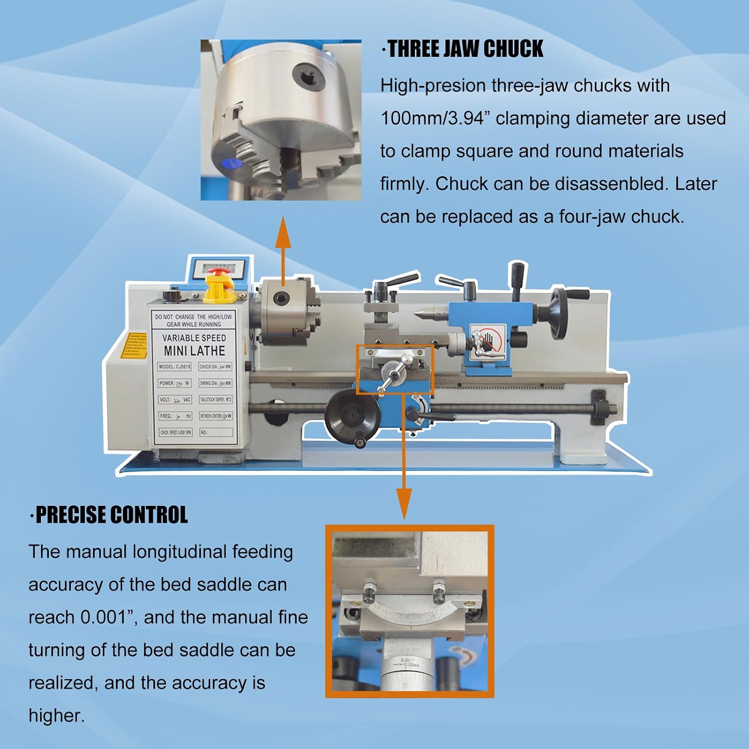
Figure 5.1: The three-jaw chuck for clamping workpieces.
The 100mm (3.94") three-jaw chuck is used to clamp square and round materials firmly. To secure a workpiece:
- Insert the chuck key into one of the chuck keyholes.
- Rotate the chuck key to open or close the jaws.
- Insert the workpiece and tighten the jaws evenly using all three keyholes to ensure a secure and centered grip.
- Remove the chuck key before starting the machine.
The chuck can be disassembled for cleaning or replacement with a four-jaw chuck if needed.
5.3 Precise Control and Bed Saddle Adjustment

Figure 5.2: Bed saddle and fine-tuning mechanism for precise control.
The manual longitudinal feeding accuracy of the bed saddle can reach 0.001 inches. This allows for fine adjustments during machining operations. Use the bed saddle fixed handle to lock its position and the fine-tuning mechanism for precise manual adjustments.
5.4 Tailstock Adjustment
The tailstock can be moved along the lathe bed and locked into position using the tailstock fixed handle. The tailstock quill can be extended or retracted using the tailstock extends length handle. The MT2 taper allows for various tailstock accessories. Adjust set screws for accurate alignment.
5.5 Thread Cutting
This machine is capable of cutting metric threads ranging from 0.5mm to 2.5mm. Refer to the parameter table on the machine for specific gear settings required for different thread pitches. Ensure correct gear engagement before initiating thread cutting operations.
5.6 Applications
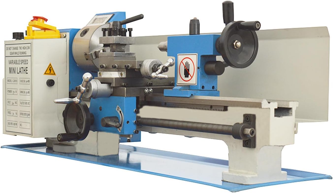
Figure 5.3: The CJ0618 Metal Lathe performing a turning operation.
The miniature lathe is primarily used for processing the end face of various rotary surfaces and rotating bodies. This includes turning inside and outside cylindrical surfaces. Its versatile processing functions make it suitable for DIY projects, educational purposes, and turning small components.
6. Maintenance
Regular maintenance ensures the longevity and optimal performance of your lathe.
6.1 Cleaning
- After each use, clean all chips and debris from the lathe bed, carriage, and other surfaces.
- Use a brush or compressed air. Avoid using bare hands to remove sharp chips.
- Wipe down all exposed metal surfaces with an oily rag to prevent rust.
6.2 Lubrication
- Regularly lubricate all sliding surfaces (bedways, cross slide, top slide) with appropriate machine oil.
- Apply oil to the leading screw and other threaded components.
- Check and lubricate gears as necessary, especially after heavy use.
6.3 Gear Maintenance
Periodically inspect the all-metal gears for wear or damage. Ensure they are properly meshed and lubricated. Replace worn gears promptly to maintain precision.
6.4 Spindle Accuracy Check
Periodically check the spindle accuracy (0.01mm) using a dial indicator. If significant runout is detected, consult a qualified technician.
7. Troubleshooting
This section addresses common issues you might encounter during operation.
| Problem | Possible Cause | Solution |
|---|---|---|
| Machine does not power on | No power supply; Emergency stop engaged; Faulty switch | Check power connection; Release emergency stop; Inspect switches. |
| Spindle not rotating | Speed knob at zero; Motor issue; Belt slippage | Adjust speed knob; Consult technician; Check belt tension. |
| Excessive vibration or noise | Unbalanced workpiece; Loose components; Worn bearings | Balance workpiece; Tighten fasteners; Inspect and replace bearings. |
| Inaccurate cuts | Loose tool post; Worn lead screw; Misaligned tailstock | Tighten tool post; Inspect lead screw; Realign tailstock. |
| Feed mechanism not engaging | Feed lever not fully engaged; Damaged gears | Ensure lever is fully engaged; Inspect and replace gears. |
8. Warranty and Support
8.1 Return Policy
This product is subject to a 30-day easy return policy for refund or replacement, as per the seller's terms.
8.2 Protection Plans
Optional protection plans, such as a 4-Year Protection Plan or a Complete Protect monthly plan, may be available for extended coverage. Please refer to your purchase documentation for details on these plans.
8.3 Customer Support
For technical assistance, parts, or warranty claims, please contact BREVELTION customer support. Refer to your product packaging or purchase invoice for specific contact information.