1. Product Overview
This manual provides essential information for the installation, operation, and maintenance of the BOATCON Remote Control-4000 Gen II 8M0030550 Side Mount for Mercury Outboard Engine. This control box is designed for embedded right-hand side installation and features power trim, an engine stop switch, and requires Generation 2 control cables.
Key Features:
- Replacement for Mercury OEM part number 8M0030550.
- Integrated power trim switch for convenient engine adjustment.
- Engine stop switch for immediate shutdown.
- Flameout rope for emergency engine stop.
- Pull-to-open console mechanism.
Package Contents:
The package includes the main remote control box assembly, power trim switch, engine stop switch, flameout rope, and various installation hardware. Refer to the image below for a visual representation of the included components.


2. Setup and Installation
This control box is designed for embedded right-hand side mounting. Proper installation is crucial for safe and reliable operation. It is recommended that installation be performed by a qualified marine technician.
Installation Steps (General Guidance):
- Preparation: Ensure the engine is off and the battery is disconnected before beginning installation. Gather all necessary tools.
- Mounting Location: Select a suitable right-hand side mounting location on your boat's console or gunwale, ensuring sufficient clearance for the control lever's full range of motion and access to the internal mechanism.
- Drilling: Carefully mark and drill the necessary holes for mounting the control box and routing the control cables and wiring. Refer to the provided template or manual page for precise measurements.
- Cable Connection: Connect the Generation 2 control cables to the engine and the control box. Ensure secure and proper routing to prevent kinking or interference.
- Electrical Connections: Connect the power trim switch wiring, engine stop switch wiring, and any other electrical connections as per your engine's wiring diagram.
- Secure Mounting: Mount the control box securely to the chosen location using the provided hardware.
- Testing: After installation, perform thorough functional tests of the throttle, shift, power trim, and engine stop switch before operating the vessel.


3. Operating Instructions
The BOATCON Remote Control-4000 Gen II provides smooth and easy operation for your Mercury outboard engine. Familiarize yourself with the control lever's movement and switch functions before operating your vessel.
Throttle and Shift Operation:
- Neutral (N): The control lever is in the upright, vertical position. The engine is running but not engaged in gear.
- Forward (F): Push the control lever forward approximately 32 degrees from neutral to engage forward gear. Further pushing the lever forward will increase throttle.
- Reverse (R): Pull the control lever backward approximately 32 degrees from neutral to engage reverse gear. Further pulling the lever backward will increase throttle in reverse.
- Throttle Range: The throttle opens progressively as the lever is moved further from the neutral position in either forward or reverse.
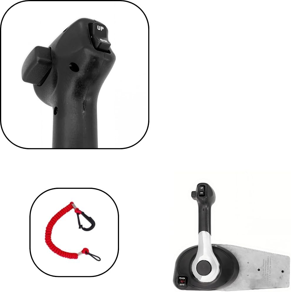
Power Trim and Tilt Switch:
The power trim and tilt switch is located on the control lever grip for easy access.
- UP Button: Push the "UP" button to tilt the outboard motor upwards.
- DN Button: Push the "DN" button to tilt the outboard motor downwards.

Engine Stop Switch and Flameout Rope:
- The engine stop switch is a safety feature for immediate engine shutdown.
- The flameout rope (lanyard) is designed to automatically stop the engine if the operator is thrown from the helm. Always attach the flameout rope to yourself or your clothing when operating the vessel.
4. Maintenance
No specific maintenance instructions for the control box itself are provided. However, regular inspection of all moving parts, cables, and electrical connections is recommended to ensure optimal performance and safety. Keep the control box clean and free from salt residue or debris.
5. Troubleshooting
No specific troubleshooting information is provided in the product details. If you encounter issues with the control box, ensure all connections are secure and undamaged. For complex problems, consult a qualified marine technician.
6. Specifications
| Attribute | Value |
|---|---|
| Brand | BOATCON |
| Model Number | 8M0030550 |
| OEM Part Number | 8M0030550 |
| Item Weight | 8.8 Pounds |
| Color | Black |
| Material | Aluminum |
| Engine Type | 4 Stroke |
| Recommended Uses | For Inflatable Boats |
| Voltage | 12 Volts (DC) |
| Mounting Type | Side Mount |
| Fuel Type | Gasoline |
| Package Dimensions | 15.15 x 8.07 x 6.5 inches |
7. Warranty and Support
This product comes with a 60-day warranty. For returns, a 15-day hassle-free return policy is offered. For technical support or warranty claims, please contact BOATCON customer service through your purchase platform or the official BOATCON website.