1. Product Overview
The JMT Protoss-PE10-M DC is an industrial-grade RS232 to WiFi serial server from the Protoss series, designed for data collection and wireless adaptation in various industrial applications. It features rail mounting for easy integration into electrical distribution boxes.
1.1 Key Features
- PC + ABS Material: Lightweight and portable design.
- V0 Flame Retardant: Ensures safety and reliability.
- Embedded Terminal: Small size for space-saving installations.
- Convenient Network Port: Located under the product to prevent dust accumulation and ease cable connection.

Figure 1: Product Features and Port Overview. This image illustrates the four key advantages of the Protoss-PE10-M DC, including its PC+ABS material, V0 flame retardant rating, embedded terminal design, and the convenient placement of the network port. It also shows a detailed view of the RS232_A+, GND, RS232_B- terminals and the RJ45 Ethernet port, along with power input options (100~240VAC or 9~50VDC).
2. Installation
2.1 Rail Mounting
The Protoss-PE10-M DC is designed for standard rail installation, offering a flexible and compact solution. The installation process involves three simple steps to secure the device within a distribution box.

Figure 2: Rail Type Serial Server Installation. This image demonstrates the Protoss-PE10-M DC mounted on a standard DIN rail, highlighting its compact design and ease of installation.
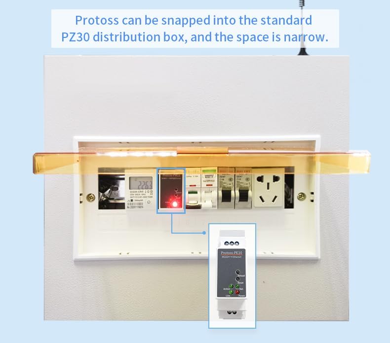
Figure 3: Installation in a PZ30 Distribution Box. This image shows the Protoss-PE10-M DC snapped into a standard PZ30 distribution box, illustrating how it fits into narrow spaces alongside other electrical components.
2.2 Power Supply Connection
The Protoss-PE10-M model is designed for environments where a switching power supply is already installed in the electrical distribution box to power sensing devices or instruments. If the existing switching power supply voltage and output power meet the requirements of the Protoss rail wizard product, it can be connected to the same switching power supply.
Important: The power supply is not included with this product.

Figure 4: Power Supply Wiring Diagram (Protoss-PE10-M). This image contrasts the wiring for Protoss-PE10-H (AC direct connection) and Protoss-PE10-M (DC connection via an existing switching power supply). For the Protoss-PE10-M, it shows the device connected to a switching power supply that converts AC to DC, indicating the AC input to the power supply and the DC input to the Protoss device.
3. Operating Modes
The Protoss-PE10-M DC supports various operating modes for flexible data communication.
3.1 Quick Serial Command Configuration
This mode allows for rapid parameter configuration of the IoT factory device. The serial port device sends a specific string of data packets, conforming to predefined parameter configuration rules, to the serial port of the IoT factory device. This enables quick, one-time parameter settings.
3.2 ModbusTCP Protocol
The device supports the conversion between ModbusRTU and ModbusTCP protocols. This is suitable for connecting serial PLCs and for communication between ModbusRTU equipment and a PC using configuration software.
3.3 HTTP Client
In HTTP Client mode, data packets received by the device through the serial port are directly sent to a web server using the HTTP protocol. This is practical for B/S architecture systems, allowing data storage operations to be realized using scripting languages like PHP and ASP, without requiring the development of a TCP Server.

Figure 5: Operating Mode Overview. This diagram illustrates the three primary operating modes: Quick Serial Command Configuration (showing MCU serial communication to the device and network communication to Vcom/PC controlled software), ModbusTCP Protocol (showing serial device to Modbus RTU and Modbus TCP to PC), and HTTP Client (showing multiple devices sending HTTP data to a Web Server, which then interacts with program languages and a database).
4. Software Architecture
The Protoss-PE10-M DC integrates a comprehensive software architecture to manage Ethernet serial server functions and facilitate remote management.

Figure 6: Software Architecture Diagram. This diagram details the Ethernet Serial Server Function, including multiple sockets (TCP Server/UDP Server, TCP Client/UDP Client with Transparent Transmission Mode), Wildcard Registration Package, Custom Heartbeat Package, HTTP Assembly/Parse, HTTP POST/GET, ModbusRTU Polling, MQTT/TCP/UDP, ModbusMaster Function, Big Data Transfer, Custom HIS Script, and All IoT Function support. It also shows connections to user service cloud platforms, remote management via IOTService, High Flying IOTBridge platform, and user computer IOT-Service for local discovery and configuration.
5. Applications
The Protoss-PE10-M DC is suitable for various industrial applications requiring reliable data transmission and remote control.
5.1 Unattended Weighing
Connect the Protoss-PE10-M DC to a gate system. The control center can then remotely control the gateway switch via Ethernet, enabling unattended weighing operations.
5.2 Power Data Network Transmission
When installed in an electrical distribution box, the device facilitates remote meter reading and remote payment for rail spirit and rail meter systems.

Figure 7: Example Applications. This image illustrates two primary applications: Unattended Weighing, where the Protoss-PE10 is connected to a gate for remote control via Ethernet, and Power Data Network Transmission, showing the device installed in a distribution box for remote meter reading and payment.
6. Specifications
| Feature | Description |
|---|---|
| Model | Protoss-PE10-M DC |
| Interface | RS232 to WiFi/Ethernet |
| Material | PC + ABS (V0 Flame Retardant) |
| Power Input | 9-50VDC (for Protoss-PE10-M) |
| Special Functions | Script Secondary Development, Firmware Upgrade, Network Remote Upgrade, KeepAlive, Parameter Import/Export, Modbus Master, Custom Registration Package, Custom Data Heartbeat, 3-way Socket |
| Manufacturer | HF |
| ASIN | B0CJNNL77B |
7. Maintenance
To ensure optimal performance and longevity of your Protoss-PE10-M DC, follow these general maintenance guidelines:
- Keep the device clean and free from dust and debris.
- Ensure proper ventilation around the device to prevent overheating.
- Regularly check all cable connections for secure fit.
- Perform firmware updates as recommended by the manufacturer to benefit from new features and security enhancements.
8. Troubleshooting
If you encounter issues with your Protoss-PE10-M DC, consider the following basic troubleshooting steps:
- No Power: Verify that the DC power supply is correctly connected and providing the specified voltage (9-50VDC). Check the power indicator light on the device.
- No Network Connection: Ensure the Ethernet cable is securely connected to the RJ45 port and the network is active. Check the 'Link' and 'Net' indicator lights.
- Serial Communication Issues: Confirm that the RS232 connections (A+, GND, B-) are correct and that the serial port settings (baud rate, data bits, parity, stop bits) match between the device and the connected equipment.
- Configuration Problems: If parameters are not applying correctly, try using the Quick Serial Command Configuration mode or refer to the detailed software configuration guide (not included in this basic manual) for advanced settings.
- Device Unresponsive: Try performing a soft reset using the 'Reset' button if available, or power cycle the device.
For persistent issues, consult the manufacturer's official support resources or contact customer service.
9. Warranty and Support
Specific warranty information for the JMT Protoss-PE10-M DC is typically provided at the point of purchase or within the product packaging. Please refer to your purchase documentation for details regarding warranty coverage and duration.
For technical support, product inquiries, or service, please visit the official JMT website or contact their customer support channels.