IOFIT RV5.5-4
IOFIT RV Series Wire Terminal Crimp Splice User Manual
Models: RV1.25-4, RV2-3, RV2-4, RV3.5-4, RV5.5-4
Introduction
This manual provides instructions for the safe and effective use of IOFIT RV Series Wire Terminal Crimp Splices. These terminals are designed for reliable electrical connections, featuring PVC insulation and a circular round cold press design. They are suitable for various wire sizes, ensuring a secure and durable splice.
The RV series includes models RV1.25-4, RV2-3, RV2-4, RV3.5-4, and RV5.5-4, each designed for specific wire gauges and screw hole diameters.
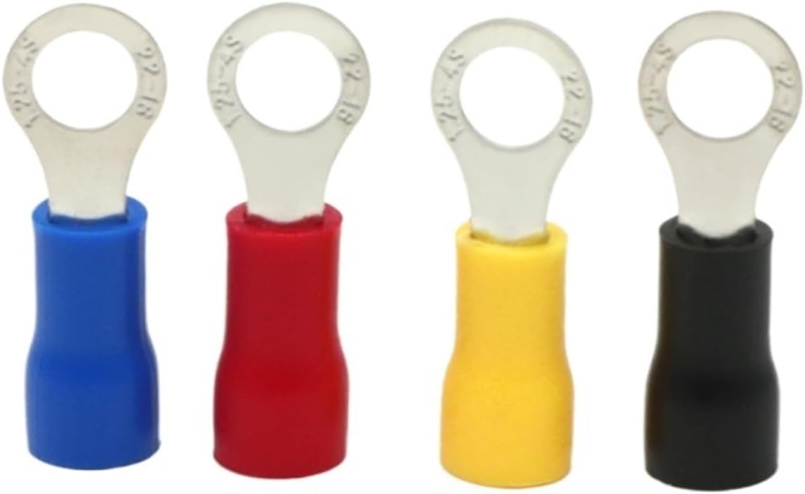
Image: An assortment of IOFIT RV series wire terminals, showcasing different colors (blue, red, yellow, black) and their distinct ring shapes for various applications.
Product Specifications
| Feature | Detail |
|---|---|
| Model Number | RV Type (RV1.25-4, RV2-3, RV2-4, RV3.5-4, RV5.5-4) |
| Type | Splice, Ring Terminal |
| Material | Brass (Tin-plated) |
| Insulator Material | PVC |
| Colors Available | Black, Red, Yellow, Blue |
| Connector Type | Crimp |
| Packing | 50pcs/bag |
| Country of Origin | China |
Dimensional Specifications (Unit: mm)
| Model | Total Length | Screw Hole Dia | Wire Through Depth | Suit for Wire Size | Board Length | Board Width | Board Thickness |
|---|---|---|---|---|---|---|---|
| RV1.25-4 | 18.6 | 4.1 | 10.1 | 0.5-1.5mm² | 8.5 | 6.50 | 0.5 |
| RV2-3 | 18.5 | 3.2 | 10.3 | 1.5-2.5mm² | 8.2 | 5.60 | 0.5 |
| RV2-4 | 19.0 | 4.0 | 10.2 | 1.5-2.5mm² | 8.8 | 6.60 | 0.5 |
| RV3.5-4 | 23.5 | 4.0 | 13.0 | 2.5-4.0mm² | 10.5 | 7.00 | 0.7 |
| RV5.5-4 | 22.9 | 4.0 | 13.1 | 4.0-6.0mm² | 9.8 | 7.20 | 0.7 |
Note: Size tolerance: ±0.1mm. The specification is for reference only.

Image: A detailed table outlining the specifications for various RV series terminals, including total length, screw hole diameter, wire through depth, and suitable wire sizes. Below the table, another image shows a row of four different colored terminals.
Individual Model Dimensions

Image: Detailed dimensions for the RV1.25-4 terminal, suitable for 0.5-1.5mm² wire, with a 4.1mm screw hole diameter.

Image: Detailed dimensions for the RV2-3 terminal, suitable for 1.5-2.5mm² wire, with a 3.2mm screw hole diameter.

Image: Detailed dimensions for the RV2-4 terminal, suitable for 1.5-2.5mm² wire, with a 4.0mm screw hole diameter.
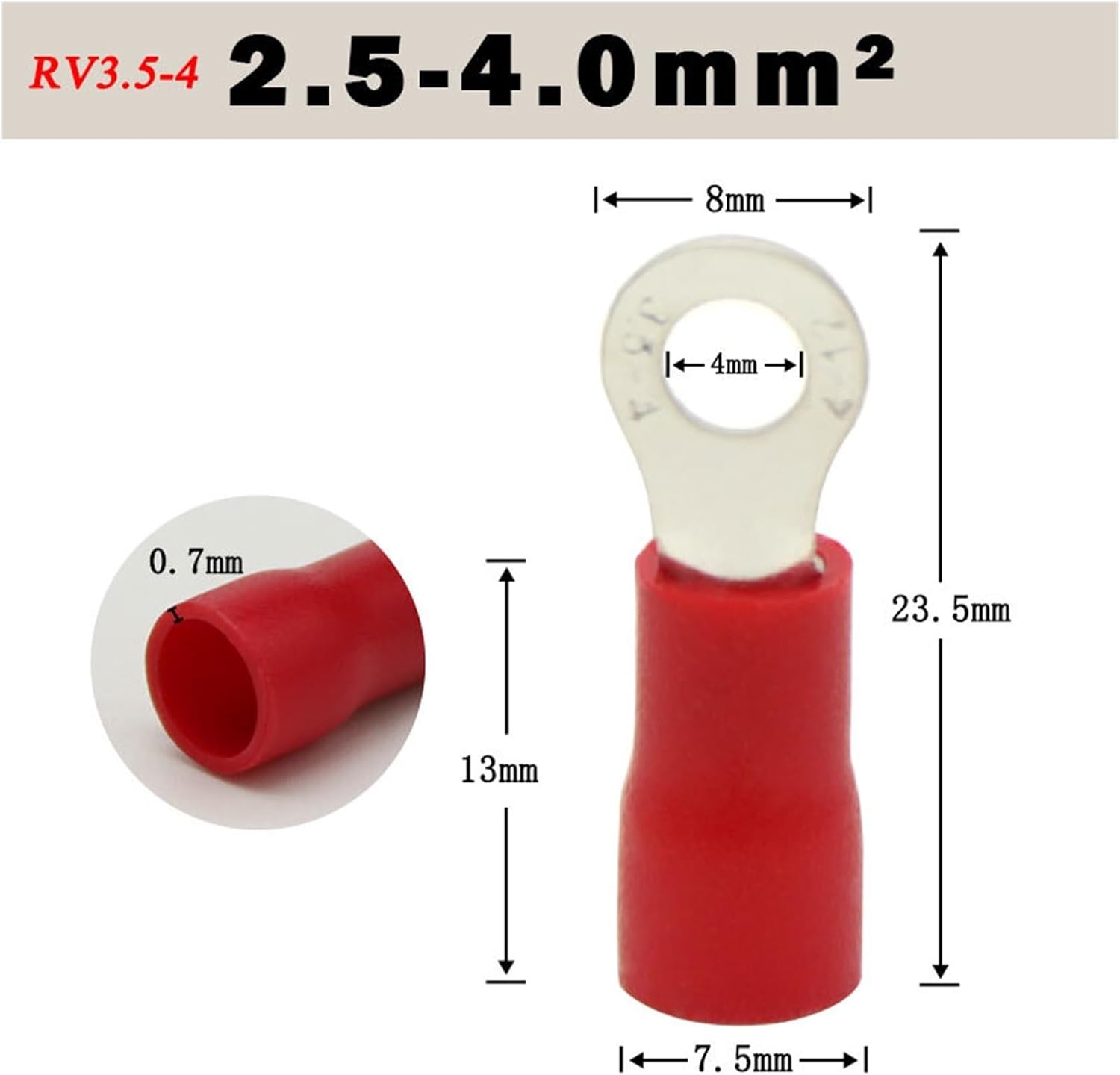
Image: Detailed dimensions for the RV3.5-4 terminal, suitable for 2.5-4.0mm² wire, with a 4.0mm screw hole diameter.

Image: Detailed dimensions for the RV5.5-4 terminal, suitable for 4.0-6.0mm² wire, with a 4.0mm screw hole diameter.
Setup and Preparation
Safety Precautions
- Always disconnect power to the circuit before working with electrical wires.
- Wear appropriate personal protective equipment (PPE), such as safety glasses and insulated gloves, when handling electrical components.
- Ensure your work area is clean, dry, and well-lit.
- Use tools that are in good condition and appropriate for the task.
Tools Required
- Wire Strippers: To remove insulation from the wire ends.
- Crimping Tool: A dedicated crimping tool suitable for insulated terminals (often color-coded to match terminal insulation).
- Wire Cutters: To cut wires to the desired length.
- Multimeter (Optional): For verifying circuit integrity after installation.
Selecting the Correct Terminal
Choose the appropriate RV series terminal based on the wire gauge (mm²) and the screw or stud size (hole diameter) you will be connecting to. Refer to the "Product Specifications" section for detailed compatibility information.
Operating Instructions: Crimping Process
- Prepare the Wire: Using wire strippers, carefully strip approximately 8-10mm (0.3-0.4 inches) of insulation from the end of the wire. Ensure the stripped wire length is sufficient to fully enter the metal barrel of the terminal without insulation being crimped.
- Insert Wire into Terminal: Insert the stripped end of the wire into the metal barrel of the selected RV series terminal. Make sure all wire strands are inside the barrel and no stray strands are protruding. The insulation of the wire should butt up against the insulation of the terminal.
- Position for Crimping: Place the terminal, with the wire inserted, into the correct crimping die of your crimping tool. For insulated terminals, crimping tools often have color-coded dies (e.g., red, blue, yellow) that correspond to the terminal's insulation color and wire gauge range. Ensure the metal barrel of the terminal is fully seated in the crimping die.
- Perform the Crimp: Squeeze the handles of the crimping tool firmly and completely until the crimp cycle is finished. A proper crimp will securely fasten the wire within the terminal's barrel.
- Inspect the Crimp: After crimping, visually inspect the connection. The crimp should be tight and uniform. Gently pull on the wire to ensure it is securely held by the terminal. The insulation of the terminal should be crimped onto the wire's insulation, providing strain relief.
- Connect the Terminal: Once crimped, the ring terminal can be connected to a screw or stud. Ensure the connection point is clean and secure.
Note: A good crimp is essential for a reliable electrical connection. An improper crimp can lead to resistance, overheating, or disconnection.
Care and Maintenance
- Storage: Store unused terminals in a dry, cool place, away from direct sunlight and moisture, to prevent corrosion and degradation of the insulation. Keep them in their original packaging or a sealed container.
- Handling: Handle terminals with clean hands to avoid transferring oils or contaminants that could affect conductivity or insulation over time.
- Inspection: Before use, inspect terminals for any signs of damage, corrosion, or deformation. Do not use damaged terminals.
Troubleshooting Common Issues
- Issue: Wire pulls out of terminal after crimping.
- Possible Cause: Incorrect crimping tool used, insufficient crimping force, wrong size terminal for wire, or wire not fully inserted.
- Solution: Ensure you are using a crimping tool designed for insulated terminals and that the correct die size is selected. Apply firm, complete pressure during crimping. Verify the wire gauge matches the terminal's specifications. Ensure the wire is fully inserted into the terminal barrel before crimping.
- Issue: Terminal insulation is damaged after crimping.
- Possible Cause: Incorrect crimping die used, or excessive force applied.
- Solution: Use the appropriate color-coded crimping die for the terminal. Apply firm but controlled pressure. Discard and replace any terminals with damaged insulation.
- Issue: Difficulty inserting wire into terminal.
- Possible Cause: Wire strands are splayed, or wire gauge is too large for the terminal.
- Solution: Twist the wire strands tightly before insertion. Ensure the wire gauge is within the specified range for the terminal model.
Warranty and Support
For information regarding product warranty or technical support, please refer to the product packaging or contact IOFIT customer service directly through their official website or the retailer from whom the product was purchased. Specific warranty terms may vary by region and retailer.
Manufacturer: IOFIT