FTVOGUE GRV8-05
FTVOGUE GRV8-05 3-Phase Voltage Monitoring Relay Instruction Manual
Model: GRV8-05 / M265
1. Introduction
This manual provides comprehensive instructions for the installation, operation, and maintenance of the FTVOGUE GRV8-05 3-Phase Voltage Monitoring Relay. This device is designed to monitor 3-phase 4-wire systems for voltage anomalies, phase sequence, and phase failure, ensuring the protection and reliable operation of connected equipment.
2. Safety Information
WARNING: Electrical installation and maintenance should only be performed by qualified personnel. Failure to follow these instructions may result in electric shock, fire, or serious injury.
- Always disconnect power before installing or servicing the device.
- Ensure all wiring conforms to local and national electrical codes.
- Do not operate the device if it appears damaged.
- Verify correct voltage and current ratings before connection.
3. Product Overview and Features
The FTVOGUE GRV8-05 is a compact and versatile 3-phase voltage monitoring relay. Its key features include:
- True RMS Measurement: Provides accurate voltage monitoring.
- Adjustable Rated Voltage: Offers 8 selectable rated voltage settings (127-265V P-N).
- LED Indicators: Green LED for power, Red LED for relay status.
- Compact Design: Small volume, suitable for 35mm DIN rail mounting.
- Protection Functions: Monitors for overvoltage, undervoltage, voltage unbalance, phase sequence, and phase failure.
- Adjustable Delay Time: Configurable action delay time from 0.1 to 10 seconds.

Figure 3.1: Front and side view of the FTVOGUE GRV8-05 relay, showing input terminals L1, L2, L3, N, and adjustment dials.
4. Specifications
| Parameter | Value |
|---|---|
| Function | Monitor L-N voltage (3-phase 4-wire system) |
| Monitoring Terminal | L1-L2-L3-N |
| Power Supply | L1-N |
| Rated Working Voltage (P-N) | 127-132-138-220-230-240-254-265V |
| Rated Power Frequency | 45Hz-65Hz |
| Measuring Range | 101V-318V |
| Voltage Threshold Range | 2%-20% (of rated voltage) |
| Voltage Fixed Lag Rate | 2% |
| Voltage Measurement Error | ±1% |
| Power-on Delay Time | 0.5s |
| Knob Setting Accuracy | 10% |
| Reset Time | 1s |
| Temperature Fluctuation Error | 0.05%/°C, at 20°C |
| Output | 1 x SPDT; 10A/AC1; 250VAC/24VDC |
| Minimum Switching Power | 500mW |
| Overvoltage Protection | 2%-20% |
| Undervoltage Protection | -20%-2% |
| Unbalanced Voltage Protection | 8% |
| Action Delay Time | 0.1-10s adjustable |
| Phase Sequence Protection | Yes |
| Phase Failure Protection | Yes |
| Power Indicator | Green LED |
| Output Relay Indication | Red LED |
| Mechanical Life | 1x10⁷ operations |
| Mounting Method | 35mm DIN rail mounting |
| Mount Altitude | ≤2000m |
| Weight | Approx. 76g / 2.7oz |
| Dimensions (L x W x H) | 95mm x 18mm x 64mm (approx. 3.7in x 0.7in x 2.5in) |

Figure 4.1: Dimensions and indicator locations of the GRV8-05 relay.
5. Setup and Installation
5.1 Mounting
The GRV8-05 relay is designed for 35mm DIN rail mounting. Ensure the mounting location is free from excessive vibration, moisture, and extreme temperatures, and allows for adequate ventilation.
5.2 Wiring Diagram
Refer to the following wiring diagram for proper connection of the GRV8-05 relay to your 3-phase 4-wire system and the controlled load.
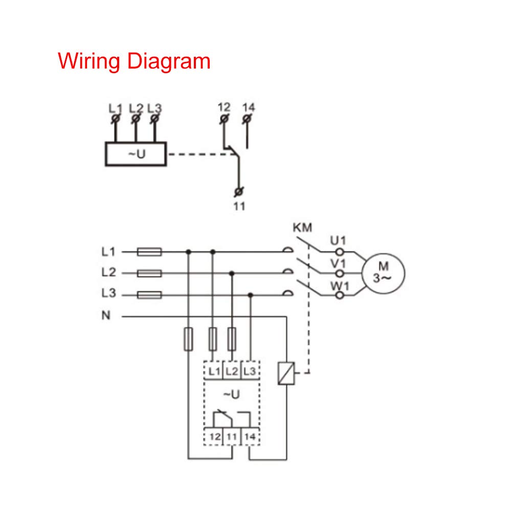
Figure 5.1: Standard wiring diagram for the GRV8-05 relay, showing connections for L1, L2, L3, N, and output contacts 11, 12, 14 to a motor (M) via a contactor (KM).
Connection Steps:
- Connect the three phase lines (L1, L2, L3) and the neutral line (N) to the corresponding input terminals on the relay. The power supply for the relay itself is taken from L1-N.
- Connect the output contacts (11, 12, 14) to the control circuit of the equipment you wish to protect (e.g., a motor contactor KM). Terminal 11 is common, 12 is normally closed (NC), and 14 is normally open (NO).
- Ensure all connections are secure and properly insulated.
6. Operating Instructions
The GRV8-05 features several adjustable parameters to customize its monitoring behavior. These are set using the rotary knobs on the front panel.

Figure 6.1: Close-up view of the adjustment knobs for rated voltage (Un), overvoltage (U>), undervoltage (U<), voltage unbalance (U%), and action delay time (Tt).
6.1 Setting Rated Voltage (Un)
Use the "Un" knob to select the nominal phase-to-neutral voltage of your system. Available settings are 127V, 132V, 138V, 220V, 230V, 240V, 254V, and 265V.
6.2 Setting Overvoltage (U>) and Undervoltage (U<) Thresholds
The "U>" knob sets the overvoltage threshold as a percentage above the rated voltage (Un), ranging from 2% to 20%. The "U<" knob sets the undervoltage threshold as a percentage below the rated voltage (Un), ranging from -20% to -2%.
6.3 Setting Voltage Unbalance (U%) Threshold
The "U%" knob adjusts the voltage unbalance threshold, typically set at 8% as per specifications.
6.4 Setting Action Delay Time (Tt)
The "Tt" knob sets the delay time before the relay acts upon detecting a fault condition. This can be adjusted from 0.1 seconds to 10 seconds to prevent nuisance tripping from momentary voltage fluctuations.
6.5 LED Indicators
- Green LED: Indicates power supply to the relay.
- Red LED: Indicates the status of the output relay. It illuminates when the relay is tripped due to a detected fault (overvoltage, undervoltage, unbalance, phase sequence error, or phase failure).
7. Maintenance
The FTVOGUE GRV8-05 relay is designed for long-term, maintenance-free operation. However, periodic checks are recommended:
- Visual Inspection: Periodically inspect the relay for any signs of physical damage, discoloration, or loose connections.
- Cleaning: If necessary, gently clean the exterior of the device with a dry, soft cloth. Do not use solvents or abrasive cleaners.
- Functionality Check: If possible and safe to do so, periodically test the relay's tripping function by simulating a fault condition (e.g., temporarily disconnecting a phase, if your system allows for safe testing).
8. Troubleshooting
| Problem | Possible Cause | Solution |
|---|---|---|
| Green LED Off | No power supply to L1-N terminals. | Check input power supply and wiring to L1 and N terminals. |
| Red LED On, Relay Tripped | Voltage fault (over/under, unbalance), phase sequence error, or phase failure detected. |
|
| Relay Not Tripping on Fault | Incorrect settings or internal fault. |
|
9. Support and Warranty
For technical assistance or warranty inquiries, please contact your vendor or the manufacturer, FTVOGUE. Please have your product model (GRV8-05) and purchase information ready when contacting support.
Manufacturer: FTVOGUE
Item Model Number: FTVOGUE067gemh9an
Ask a question about this manual
Ask about setup, troubleshooting, compatibility, parts, safety, or missing instructions. Manuals+ will review the question and use this page’s manual context to help answer it.