
Introduction
This manual provides essential information for the proper setup, operation, and maintenance of your COOL RACING RXF1221 Micro Receiver. Designed for compatibility with Futaba S-FHSS and TM-FH RF Module control systems, this micro receiver offers reliable performance for various RC applications, including Mini-Z and mini aircraft.
Product Features
- Professional Onboard Patch Antenna: Equipped with a high-quality PA to ensure excellent receiving sensitivity in a compact size.
- Integrated Stabilizing Circuit: Operates with a wide voltage range (3.5V to 8.4V, supporting 1-2S Lipo) to prevent signal loss due to sudden low voltage.
- Lightweight and Micro Size: Ideal for applications where space and weight are critical, such as Mini-Z or mini aircraft.
- Full 4-Channel Output: Provides 4 independent output channels for versatile control.
Specifications
- Model: RXF1221
- Material: Plastic
- Color: Black
- Dimensions: 26mm × 16.5mm × 7.5mm
- Working Voltage: 3.5V to 8.4V
- Output Channels: 4CH

Image: RXF1221 Micro Receiver with its dimensions clearly marked (26mm length, 16.5mm width, 7.5mm height).
Setup: Binding Procedure
Follow these steps to bind your RXF1221 receiver with your Futaba S-FHSS or TM-FH compatible transmitter:
- Ensure the transmitter and receiver are within 20 inches (approximately half a meter) of each other.
- Turn on your Futaba S-FHSS/TM-FH compatible transmitter.
- Power on the RXF1221 receiver.
- Press and hold the 'Link' (BIND SW) button on the receiver for more than two (2) seconds.
- Upon successful binding, the LED on the receiver will change to a solid green.
Note: If binding fails due to environmental interference, try touching the transmitter and receiver antennas together during the binding process.
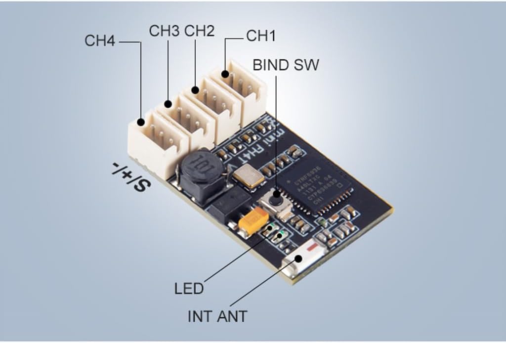
Image: Close-up view of the RXF1221 receiver's circuit board, highlighting the BIND SW (Link switch), LED indicator, CH1-CH4 ports, and the integrated antenna (INT ANT).
LED Status Indicator
The LED on the receiver provides visual feedback on its operational status:

Image: Diagram showing the RXF1221 receiver layout with an accompanying table detailing LED status indications.
| Green LED | Red LED | Status |
|---|---|---|
| Off | Solid | No signal reception |
| Solid | Off | Receiving signals |
| Blink | Off | Receiving signals but ID is unmatched |
| Alternate blink | Alternate blink | Abnormal error signal |
Compatibility
The RXF1221 Micro Receiver is compatible with Futaba S-FHSS and TM-FH RF Module control systems. This includes, but is not limited to, the following Futaba transmitters:
- Futaba 14SG
- Futaba 10J
- Futaba 8J
- Futaba 6J
- Futaba 4GRS
- Futaba 4PX
- Futaba 7PX
- Futaba 4PV
- Futaba 3PV

Image: The RXF1221 Micro Receiver, showcasing its compact design and branding indicating compatibility with Futaba S-FHSS systems.
Maintenance
To ensure the longevity and optimal performance of your RXF1221 receiver, observe the following maintenance guidelines:
- Keep Dry: Avoid exposure to moisture or liquids, as this can damage internal components.
- Clean Gently: Use a soft, dry cloth to clean the receiver. Do not use harsh chemicals or solvents.
- Protect from Impact: While durable, excessive physical shock can affect performance. Mount securely within your model.
- Temperature Control: Operate and store the receiver within recommended temperature ranges to prevent damage.
Troubleshooting
If you encounter issues with your RXF1221 receiver, consider the following common solutions:
- No Signal Reception (Red LED Solid):
- Ensure the transmitter is powered on and correctly configured.
- Re-perform the binding procedure as described in the 'Setup' section.
- Check the distance between the transmitter and receiver; reduce if too far.
- Receiving Signals but ID Unmatched (Green LED Blink):
- This indicates the receiver is picking up a signal but not from its bound transmitter. Re-bind the receiver to your specific transmitter.
- Abnormal Error Signal (Alternate Blink):
- This suggests a critical error. Power cycle both the transmitter and receiver. If the issue persists, contact customer support.
- Loss of Control/Intermittent Signal:
- Check the receiver's power supply; ensure it's within the 3.5V-8.4V range and stable.
- Inspect the antenna for any damage or obstruction.
- Avoid operating near strong sources of electromagnetic interference.