DEWIN IRAYIYEAY-GS109479-03-DEWZZQ-03
DeWin 2.2kW 220V Single-Phase Input Three-Phase Output VFD Frequency Converter User Manual
1. Introduction and Safety Warnings
This manual provides essential instructions for the safe and efficient operation of your DeWin 2.2kW 220V Single-Phase Input Three-Phase Output VFD Frequency Converter. Please read this manual thoroughly before installation, operation, or maintenance.
Important Safety Information
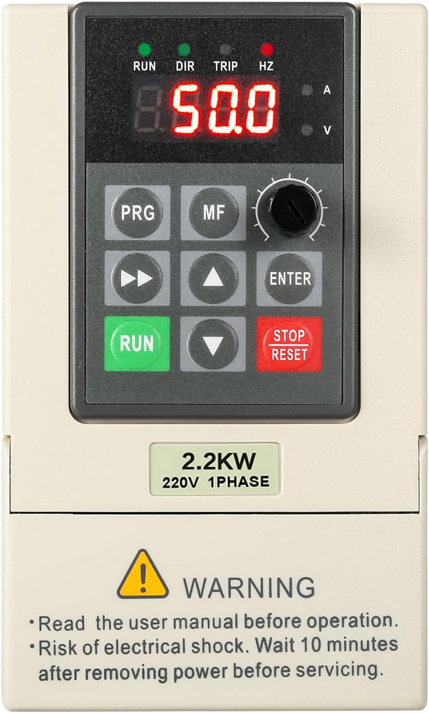
WARNING: Read the user manual before operation.
WARNING: Risk of electrical shock. Always wait at least 10 minutes after removing power before servicing the unit to allow capacitors to discharge.
Failure to follow these instructions may result in serious injury or equipment damage.
2. Product Features
The DeWin VFD Frequency Converter is designed for precise motor speed control with robust performance and safety features. Key characteristics include:
- Unique Control Method: Utilizes a unique control method to achieve high torque, high precision, a wide speed range, and overall high performance.
- Comprehensive Protection: Incorporates complete protection measures against overcurrent, overvoltage, overheating, undervoltage, and short-circuits, ensuring high reliability.
- Compact and User-Friendly: Features a small size for easy installation and is simple to operate, offering fast start/stop response and significant low-speed torque.
- High Performance and Stability: Exhibits good anti-aging and anti-tripping performance, with excellent adaptability to sudden power fluctuations, temperature changes, humidity, and dust, significantly enhancing stability.
- Integrated Heat Dissipation: Equipped with a radiator to effectively reduce and dissipate heat, ensuring stable long-term operation.


3. Specifications
Detailed technical specifications for the DeWin VFD Frequency Converter (Model: IRAYIYEAY-GS109479-03-DEWZZQ-03):
| Specification | Value |
|---|---|
| Brand | DEWIN |
| Model Number | IRAYIYEAY-GS109479-03-DEWZZQ-03 |
| Material | Flame-retardant ABS plastic |
| Communication Function | RS485 communication |
| Rated Input Voltage | Single-phase 220V |
| Rated Output Voltage | Three-phase 220V |
| Rated Power | 2.2 kW |
| Output Current | 10A |
| Factory Frequency | 50 Hz |
| Output Frequency Range | 0-999 Hz |
| Installation Method | Wall-mounted, cabinet-mounted |
| Dimensions (L x W x H) | 23 x 17 x 16 cm (approximate) |
| Item Weight | 1.12 Kilograms |
| DC Power Nature | Voltage type |
| Control Mode | V/F closed loop |
| Output Voltage Regulation Method | PAM control |
| Application Area | Assembly line, conveyor belt, etc. |

4. Setup and Wiring
Proper wiring is crucial for the safe and correct operation of the VFD. Ensure all power is disconnected before proceeding with any wiring.
4.1 Wiring Diagram

4.2 Power and Motor Connections
Connect the single-phase 220V power supply to the input terminals (R, S, T) and the three-phase motor to the output terminals (U, V, W). Ensure proper grounding.

4.3 Removable Control Panel
The control panel can be easily removed for more convenient wiring and operation, especially when connecting cables via screw terminals.

5. Operating Instructions
The VFD features an intuitive control panel for easy operation and speed adjustment.
5.1 Control Panel Overview

Familiarize yourself with the following control panel elements:
- Digital Display: Shows real-time status, frequency, current, and voltage.
- RUN/DIR/TRIP/HZ Indicators: Indicate running status, direction, fault, and frequency unit.
- PRG (Program) Key: Accesses the parameter setting menu.
- MF (Multifunction) Key: Used for various functions depending on the mode.
- Speed Knob: Adjusts the output frequency/motor speed.
- Shift Key (Left Arrow): Moves cursor or shifts digits during parameter setting.
- Up/Down Arrow Keys: Navigate menus and adjust parameter values.
- ENTER Key: Confirms selections or enters sub-menus.
- RUN Key: Starts the motor.
- STOP/RESET Key: Stops the motor or resets fault conditions.
5.2 Speed Adjustment
The VFD allows for continuous speed regulation from 0 to 999Hz, providing flexible control over your motor's operation. The speed can be easily adjusted using the dedicated speed knob on the control panel.

6. Maintenance
Regular maintenance helps ensure the longevity and reliable performance of your VFD. Always disconnect power before performing any maintenance.
- Cleaning: Keep the VFD clean and free from dust and debris. Use a soft, dry cloth for cleaning. Do not use liquid cleaners.
- Ventilation: Ensure adequate ventilation around the unit to prevent overheating. Regularly check that the radiator fins are not obstructed.
- Connections: Periodically check all wiring connections for tightness. Loose connections can lead to poor performance or damage.
- Environmental Conditions: Operate the VFD within its specified environmental conditions (temperature, humidity, dust levels) to prevent premature wear.
7. Troubleshooting
This section provides guidance for common issues. For more complex problems, consult the detailed parameter table or contact technical support.
7.1 Common Issues and Solutions
- VFD Not Powering On:
- Check the main power supply connection.
- Verify input voltage matches the VFD's rating (220V single-phase).
- Inspect fuses or circuit breakers in the power line.
- Motor Not Running:
- Ensure the RUN button has been pressed.
- Check motor wiring for correct connections (U, V, W).
- Verify that no fault (TRIP indicator) is active. Press STOP/RESET to clear faults.
- Check parameter settings for motor type and control mode.
- Motor Speed Inconsistent or Incorrect:
- Adjust the speed knob and observe the frequency display.
- Check for external control signals (e.g., analog input) if used.
- Review frequency range settings in parameters.
- Overcurrent/Overvoltage Faults:
- Check motor load; reduce if excessive.
- Verify input voltage stability.
- Ensure motor parameters are correctly set in the VFD.
If issues persist after basic troubleshooting, it is recommended to consult a qualified electrician or contact DeWin customer support.
8. Warranty and Support
Warranty information for your DeWin VFD Frequency Converter is typically provided with your purchase documentation. Please refer to those materials for details regarding warranty coverage and terms.
For technical support, service, or inquiries about replacement parts, please contact your retailer or the manufacturer directly. Provide your product model number (IRAYIYEAY-GS109479-03-DEWZZQ-03) and a detailed description of the issue to expedite assistance.
Ask a question about this manual
Ask about setup, troubleshooting, compatibility, parts, safety, or missing instructions. Manuals+ will review the question and use this page’s manual context to help answer it.