1. Introduction
The DT-830B Digital Multimeter is a versatile and portable tool designed for accurate electrical measurements. Featuring a large LCD display for clear readings up to 1999, it is an ideal instrument for laboratories, factories, radio enthusiasts, and general household use. This multimeter is capable of measuring AC/DC voltage, DC current, resistance, and performing transistor tests, making it suitable for troubleshooting automotive and household appliance issues. Its robust design includes a compact soft rubber protective cover for test leads, ensuring insulation and a non-slip grip, along with an automatic recovery overload protection circuit for enhanced safety and durability.
2. Safety Information
Please read and understand all safety instructions before operating the multimeter. Failure to follow these instructions may result in electric shock, fire, or damage to the meter or the equipment under test.
- Always ensure the correct function and range are selected before making any measurements.
- Do not exceed the maximum input values for any range. The maximum AC voltage is 750V, maximum DC voltage is 1000V, and maximum DC current is 10A.
- Exercise extreme caution when working with live circuits. Voltages above 30V AC RMS, 42V peak, or 60V DC are considered hazardous.
- Inspect test leads for damage before each use. Do not use if insulation is cracked or exposed.
- Ensure the battery cover is securely closed before operation.
- Disconnect power to the circuit and discharge all high-voltage capacitors before measuring resistance or continuity.
- Do not operate the meter if it appears damaged or is not operating properly.
3. Package Contents
Verify that all items are present in the package:
- 1 x DT-830B Digital Multimeter
- 2 x Test Leads (Red and Black)
- 1 x English User Manual
4. Product Overview
The DT-830B Digital Multimeter features a compact design with a clear LCD display and a rotary switch for function selection. Below is an illustration of the multimeter and its components.
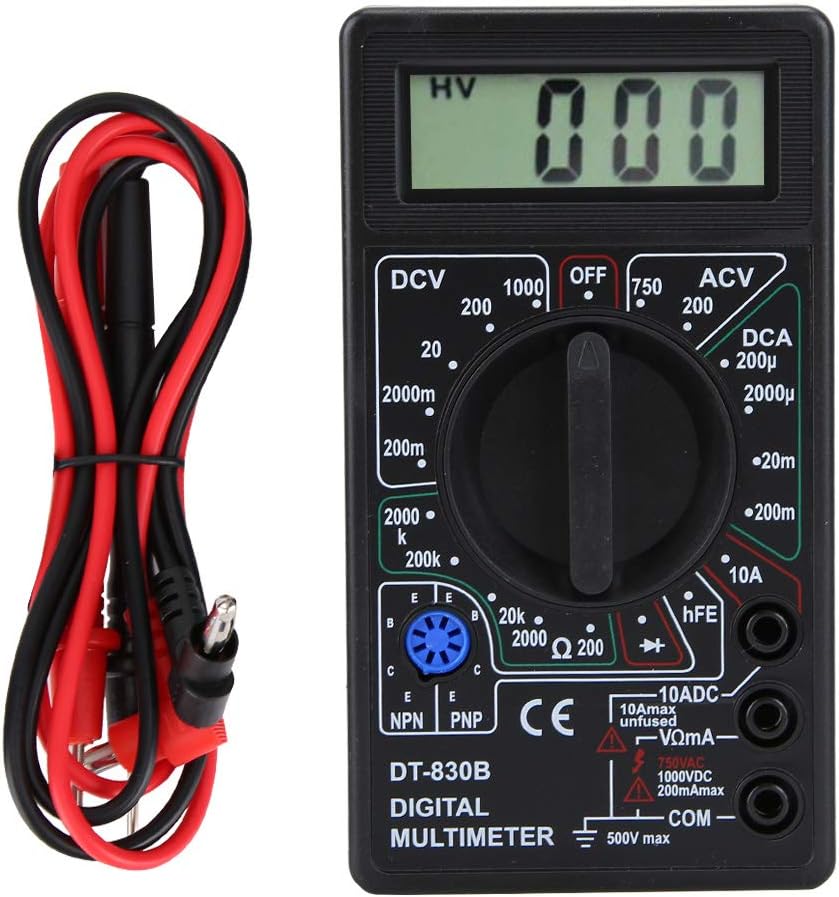
Figure 4.1: Front view of the DT-830B Digital Multimeter with its included test leads.

Figure 4.2: The DT-830B Digital Multimeter showing its approximate dimensions: 12.4cm (4.9in) length, 6.9cm (2.7in) width, and 2.4cm (0.9in) thickness.
Key Components:
- LCD Display: Shows measurement readings, units, and low battery indicator.
- Rotary Switch: Used to select measurement functions (DCV, ACV, DCA, Resistance, Transistor, OFF).
- Input Jacks:
- VΩmA Jack: Positive input for voltage, resistance, and small current measurements.
- 10ADC Jack: Positive input for 10A DC current measurements.
- COM Jack: Common (negative) input for all measurements.
- Test Leads: Red (positive) and Black (negative) leads for connecting to circuits.
- Transistor Test Socket: For hFE measurements of NPN and PNP transistors.
5. Setup
5.1 Battery Installation
The DT-830B Multimeter requires one 9V battery (not included) for operation.
- Locate the battery compartment on the back of the multimeter.
- Use a screwdriver to remove the screw securing the battery cover.
- Carefully remove the cover.
- Connect a 9V battery to the battery clips, observing correct polarity (+ and -).
- Place the battery inside the compartment and replace the cover, securing it with the screw.
5.2 Connecting Test Leads
The test leads are essential for making measurements. Always connect them correctly for the desired function.
- Insert the black test lead into the COM (common) jack. This is the negative (-) input.
- For most measurements (voltage, resistance, and small current), insert the red test lead into the VΩmA jack. This is the positive (+) input.
- For high current measurements (up to 10A DC), insert the red test lead into the 10ADC jack.

Figure 5.1: The DT-830B Multimeter with the red test lead connected to the VΩmA jack and the black test lead connected to the COM jack.
6. Operating Instructions
This section details how to perform various measurements using your DT-830B Digital Multimeter.
6.1 Measuring DC Voltage (DCV)
Use this function to measure direct current voltage in circuits.
- Set the rotary switch to the desired DCV range (e.g., 200mV, 2000mV, 20V, 200V, 1000V). If the voltage is unknown, start with the highest range (1000V) and decrease as needed for better resolution.
- Connect the red test lead to the VΩmA jack and the black test lead to the COM jack.
- Connect the test probes in parallel across the component or circuit you wish to measure.
- Read the voltage value on the LCD display. If a negative sign appears, it indicates that the polarity of the test leads is reversed relative to the circuit.
6.2 Measuring AC Voltage (ACV)
Use this function to measure alternating current voltage.
- Set the rotary switch to the desired ACV range (e.g., 200V, 750V). Start with the highest range (750V) if the voltage is unknown.
- Connect the red test lead to the VΩmA jack and the black test lead to the COM jack.
- Connect the test probes in parallel across the AC source or component.
- Read the voltage value on the LCD display.
6.3 Measuring DC Current (DCA)
Use this function to measure direct current flowing through a circuit.
- Important: To measure current, the multimeter must be connected in series with the circuit. This means breaking the circuit and inserting the meter.
- Set the rotary switch to the desired DCA range (e.g., 200uA, 2000uA, 20mA, 200mA, 10A). Start with the highest range (10A) if the current is unknown.
- For ranges up to 200mA, connect the red test lead to the VΩmA jack. For 10A measurements, connect the red test lead to the 10ADC jack. The black test lead always connects to the COM jack.
- Open the circuit where you want to measure current. Connect the red probe to the higher potential side and the black probe to the lower potential side, completing the circuit through the multimeter.
- Read the current value on the LCD display.
6.4 Measuring Resistance (Ω)
Use this function to measure the resistance of a component.
- Ensure the circuit is de-energized and all capacitors are discharged before measuring resistance.
- Set the rotary switch to the desired Resistance range (e.g., 200Ω, 2kΩ, 20kΩ, 200kΩ, 2000kΩ).
- Connect the red test lead to the VΩmA jack and the black test lead to the COM jack.
- Connect the test probes across the component whose resistance you want to measure.
- Read the resistance value on the LCD display. If the display shows '1', it indicates an open circuit or out-of-range resistance.
6.5 Transistor Test (hFE)
This function allows for testing the DC current gain (hFE) of NPN and PNP transistors.
- Set the rotary switch to the hFE position.
- Identify the Emitter (E), Base (B), and Collector (C) leads of the transistor.
- Insert the transistor leads into the corresponding holes in the NPN or PNP socket on the multimeter.
- Read the hFE value on the LCD display.
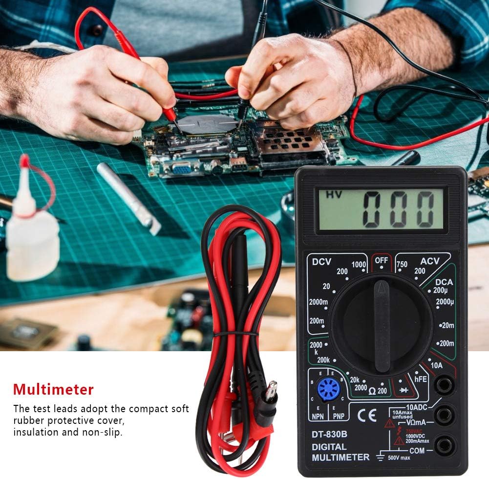
Figure 6.1: The DT-830B Multimeter being used to test components on a circuit board, demonstrating its application in electronics troubleshooting.
7. Maintenance
Proper maintenance ensures the longevity and accuracy of your multimeter.
7.1 Cleaning
Wipe the case with a damp cloth and mild detergent. Do not use abrasives or solvents. Ensure the meter is off and test leads are disconnected before cleaning.
7.2 Battery Replacement
When the battery symbol appears on the LCD display, the 9V battery needs to be replaced. Refer to Section 5.1 for battery installation instructions.
7.3 Storage
If the meter is not to be used for a long period, remove the battery to prevent leakage and damage to the meter. Store the multimeter in a cool, dry place, away from direct sunlight and extreme temperatures.
8. Troubleshooting
If you encounter issues with your multimeter, refer to the following common problems and solutions:
- No Display or Faint Display:
- Check the battery. Replace if low or dead.
- Ensure the battery is installed with correct polarity.
- Incorrect Readings:
- Verify that the correct function and range are selected for the measurement.
- Ensure test leads are securely connected to the correct input jacks.
- Check for damaged test leads.
- Ensure the circuit is de-energized when measuring resistance or continuity.
- '1' or 'OL' on Display (Resistance/Continuity):
- Indicates an open circuit or that the measured value is out of the selected range. Try a higher range if applicable.
9. Specifications
Technical specifications for the DT-830B Digital Multimeter:
| Parameter | Value |
|---|---|
| Maximum Display | 1999 |
| DC Voltage Ranges | 200mV, 2000mV, 20V, 200V, 1000V |
| AC Voltage Ranges | 200V, 750V |
| DC Current Ranges | 200uA, 2000uA, 20mA, 200mA, 10A |
| Resistance Ranges | 200Ω, 2kΩ, 20kΩ, 200kΩ, 2000kΩ |
| Transistor Test | NPN, PNP (hFE) |
| Power Supply | 9V battery (Not included) |
| Dimensions (L x W x H) | Approx. 12.4 x 6.9 x 2.4 cm (4.9 x 2.7 x 0.9 in) |
| Item Weight | Approx. 126g (4.4oz) |
| Material | Plastic + Rubber |
10. Warranty and Support
For any questions regarding the operation, maintenance, or troubleshooting of your DT-830B Digital Multimeter, please refer to this manual. If further assistance is required, please contact PerGar customer support through the retailer where the product was purchased. Please retain your proof of purchase for any warranty claims.


