1. Product Overview
The AN-5W-203 Automatic Voltage Regulator (AVR) is a sealed electronic device designed for use with electric generators. This AVR controls and automatically adjusts the generator's output voltage by regulating the excitation of the generator.
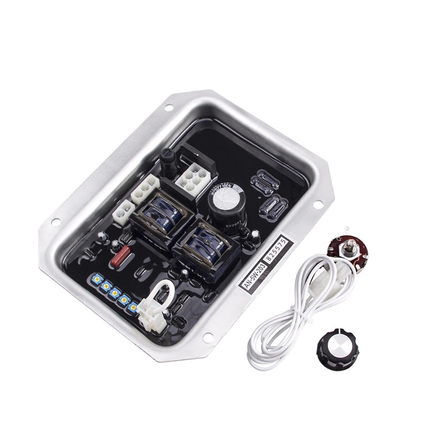
Image: The ZIPCOM AN-5W-203 Automatic Voltage Regulator module, showing its internal components and overall design.
2. Technical Specifications
- Excitation and Auxiliary Winding Input: AC 55V-220V
- Maximum Excitation Voltage Input: 120V/5ADC/10s
- Main Winding Voltage Input: 400VAC, 50Hz/60Hz
- Low Frequency Protection: Adjustable for 50/60Hz
- Generator Magnetic Field Resistance: > 5Ω
- Voltage Adjustment Rate: ±0.5%
- Voltage Adjustment Range: > 15%
- Minimum Residual Magnetic Excitation Voltage: > 5V/30Hz
- External Power Level Voltage: 12% of voltage at 1kΩ/1W
Physical Dimensions

Image: Rear view of the AVR module with key dimensions indicated in millimeters. The module measures approximately 184mm in length and 148mm in width.
- Package Dimensions: 1.18 x 0.79 x 0.39 inches
- Item Weight: 3.53 ounces
- Number of Pieces: 1
3. Safety Precautions and Installation
Installation, connection, and inspection operations must be performed by qualified professionals with appropriate technical knowledge. Ensure the regulator is installed within the generator housing or in a location not easily accessible to unauthorized personnel.
- Professional Installation: Always ensure installation, connection, and inspection are carried out by trained professionals.
- Avoid Contact During Operation: Do not touch the regulator when the generator is running to prevent dangerous accidents due to high voltage.
- Secure Mounting: Mount the AVR securely to prevent vibration-induced damage.
- Proper Ventilation: Ensure adequate ventilation around the AVR to prevent overheating.

Image: An angled view of the AVR's circuit board, showing capacitors, transformers, and connection terminals. Proper handling and connection are crucial during installation.
4. Operating Instructions
4.1 Low Frequency Protection Adjustment
The "U/F" potentiometer is used to set the low-frequency protection threshold. For a 50Hz system, low-frequency protection is typically set at 46Hz. For a 60Hz system, it is typically set at 56Hz.
- Establish Voltage: Ensure the generator is operating and producing voltage.
- Adjust Potentiometer: Slowly turn the "U/F" potentiometer counter-clockwise until the generator voltage begins to drop. This indicates that the frequency is insufficient and the low-frequency protection has activated.
- Set Desired Value: Adjust the potentiometer to the required low-frequency protection value (e.g., 46Hz for 50Hz operation or 56Hz for 60Hz operation).
When the generator operates below the set low-frequency threshold, the output voltage will decrease due to the low-frequency protection mechanism. This prevents damage to the magnetic field stator coil caused by excessive low-frequency operation.
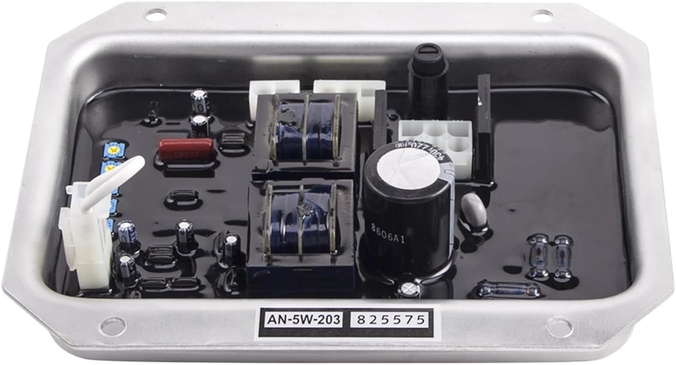
Image: A top-down view of the AVR circuit board, highlighting the various components and potential adjustment points, including the "U/F" potentiometer for frequency protection.
5. Product Features
- Integrated Solution: Includes engine voltage regulator and rectifier for comprehensive voltage control.
- High-Quality Capacitance: Ensures smooth, efficient, and reliable operation with consistent parameter performance.
- Precise Resistance: Utilizes high-precision resistance components for stable operation across a wide temperature range.
- Durable Potentiometer: Allows for smooth and easy adjustments while offering durability and resistance to damage.
- Reliable Capacitors: Equipped with high-quality capacitors for consistent performance even under demanding conditions.
6. Maintenance
The AN-5W-203 AVR is designed for reliable operation with minimal maintenance. Regular inspection of connections and the surrounding environment is recommended.
- Visual Inspection: Periodically inspect the AVR for any signs of physical damage, loose connections, or excessive dust accumulation.
- Cleanliness: Ensure the area around the AVR is clean and free from debris that could obstruct ventilation.
- Connection Integrity: Verify that all electrical connections are secure and free from corrosion.
- Environmental Conditions: Ensure the operating environment remains within specified temperature and humidity ranges to prolong the life of the unit.
7. Troubleshooting
If the generator experiences voltage instability or incorrect output, consider the following troubleshooting steps:
- Check Connections: Verify all wiring connections to the AVR are secure and correctly installed according to the generator's wiring diagram.
- Verify Input Voltage: Confirm that the excitation and auxiliary winding input voltages are within the specified range (AC 55V-220V).
- Inspect Generator Components: Check the generator's main winding voltage and magnetic field resistance for any anomalies.
- Low Frequency Protection: If the generator voltage drops unexpectedly, check the "U/F" potentiometer setting and ensure the generator's operating frequency is above the set low-frequency protection threshold.
- Professional Assistance: If issues persist after basic checks, consult a qualified technician for further diagnosis and repair.