1. Introduction
This manual provides detailed instructions for the installation, operation, and maintenance of your Tosuny LGA 1155 Micro ATX Desktop Motherboard. Please read this manual thoroughly before use to ensure proper functionality and to prevent damage. This motherboard is designed for desktop computers, supporting Intel LGA 1155 processors and DDR3 memory.

Image 1.1: Overview of the Tosuny LGA 1155 Micro ATX Desktop Motherboard, highlighting key components.
2. Key Features
- LGA 1155 CPU Slot: Supports 2nd generation Intel Core i3/i5/i7, Pentium, and Celeron series processors.
- Dual Channel DDR3 Memory: Features two DDR3 Non-ECC memory slots, supporting up to 16GB (2x 8GB) with active frequencies of 1066/1333/1600MHz.
- M.2 NVMe NGFF Support: Equipped with a high-speed M.2 interface that supports both NVMe and NGFF dual modes, allowing flexible selection between high-speed PCIe and SATA2.0 channels.
- 3-Phase Power Supply: Utilizes a stable 3-phase power design with solid-state capacitors and 24+4 pin power connectors to ensure reliable operation of motherboard accessories.
- VGA & HD Multimedia Output: Provides both VGA and HD Multimedia Interface outputs for display connectivity.
- Expansion Slots: Includes one PCI Express X16 slot for graphics cards, one PCI Express X1 slot, and one M.2 NVMe/NGFF slot.
- Connectivity: Offers 6 USB 2.0 ports, 3 SATA 2.0 ports, and a 10/100 Mbps LAN port.

Image 2.1: The motherboard showcasing its primary features and capabilities.
3. Specifications
| Brand | Tosuny |
| Model Number | Tosunye6sh8gkov4 |
| CPU Socket | LGA 1155 |
| Compatible Processors | Intel Celeron, Intel Pentium, Intel Core i3/i5/i7 (2nd Gen) |
| RAM Technology | DDR3 |
| Memory Slots | 2 (Dual Channel) |
| Max Memory Capacity | 16GB (2x 8GB) |
| Memory Clock Speed | 1066/1333/1600 MHz |
| Chipset Type | Intel H61/H67/P67/Z68/Z77 or similar |
| Storage Interfaces | 4x SATA 2.0 (3Gb/s), 1x M.2 NVMe/NGFF slot |
| LAN | 10/100 Mbps |
| USB Ports (External) | 6x USB 2.0 |
| Video Output | 1x VGA, 1x HD Multimedia Interface |
| Audio | Integrated ALC 6-channel HD audio codec, 1x 3-in-1 Audio Port (Line In/Out, Mic In) |
| Expansion Slots | 1x PCI Express X16, 1x PCI Express X1, 1x M.2 NVMe/NGFF |
| Form Factor | Micro ATX (17 x 19 cm) |
| Onboard Interfaces | 1x 24-pin ATX Power, 1x 4-pin ATX 12V Power, 2x USB headers (for 4x USB 2.0), 1x F-Audio, 1x F-Panel, 1x F-Speaker, 1x Fan connector, 1x LPC Debug connector |
| Origin | China |
4. Setup and Installation
Follow these steps carefully to install your motherboard and its components.
4.1 Motherboard Layout

Image 4.1: Detailed layout of the Tosuny LGA 1155 Micro ATX Motherboard, indicating CPU socket, RAM slots, PCIe slots, SATA ports, and I/O interfaces.
4.2 Installation Steps
- Unpacking and Initial Inspection: Carefully remove the motherboard from its packaging. Inspect for any visible damage. Ensure all components listed in the package contents are present.
- Prepare your PC case: Ensure your PC case is compatible with Micro ATX motherboards. Install the necessary standoffs for motherboard mounting.
- Install the CPU: Open the LGA 1155 socket lever. Align the CPU with the socket's notch (usually a triangle or arrow mark), gently place it into the socket without force, and then close the lever to secure it.
- Install the CPU Cooler: Apply thermal paste to the CPU (if not pre-applied on the cooler). Attach the CPU cooler according to its specific instructions, ensuring it is securely fastened and the fan cable is connected to the CPU_FAN header.
- Install RAM: Open the clips on the DDR3 memory slots. Align the RAM modules with the slots, ensuring the notch on the module matches the key in the slot. Press down firmly on both ends of the RAM stick until the clips lock into place. If installing multiple modules, refer to your CPU/motherboard manual for optimal slot population.

Image 4.2: Close-up view of the DDR3 RAM slots and SATA 2.0 ports, showing where memory modules and storage devices connect.
- Mount the Motherboard: Carefully place the motherboard into the PC case, aligning the screw holes with the installed standoffs. Secure the motherboard using appropriate screws.
- Connect Power: Connect the 24-pin ATX main power connector and the 4-pin ATX 12V CPU power connector from your power supply to the corresponding sockets on the motherboard. Ensure they are firmly seated.
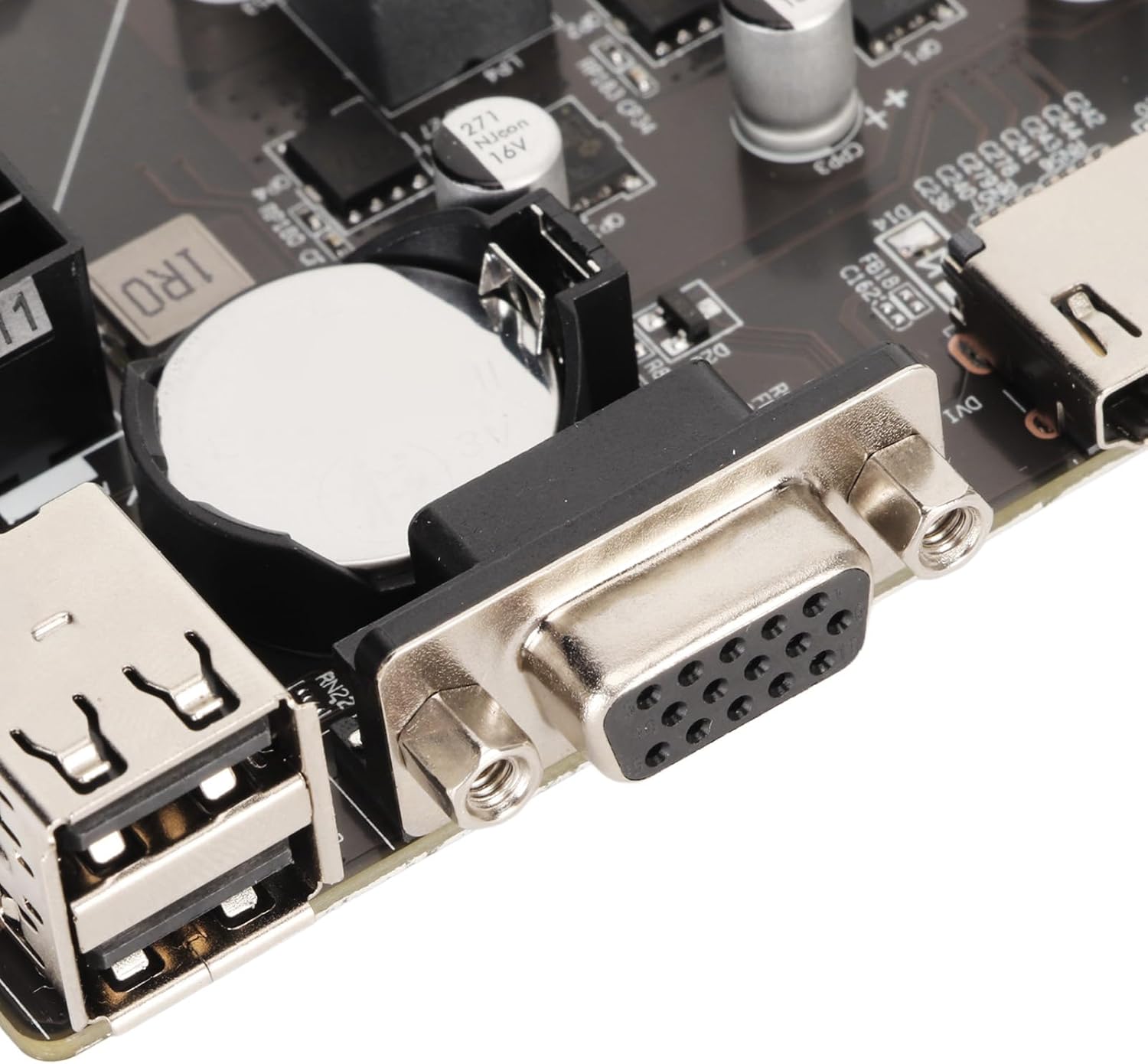
Image 4.3: The 24-pin ATX power connector, essential for providing main power to the motherboard.
- Connect Storage Devices: Connect SATA data cables from your storage drives (HDDs/SSDs) to the SATA 2.0 ports on the motherboard. If using an M.2 NVMe/NGFF drive, install it into the M.2 slot and secure it with the provided screw.
- Connect Peripherals: Connect front panel connectors (power button, reset button, power LED, HDD LED, front USB, front audio) to their respective headers on the motherboard. Connect USB 2.0 devices, VGA/HDMI display cables, and the LAN cable to the rear I/O panel.

Image 4.4: Rear I/O panel showing VGA, HD Multimedia Interface, USB 2.0, LAN, and audio ports for external device connections.
- Install Expansion Cards: If using a dedicated graphics card or other PCIe cards, install them into the PCI Express X16 or X1 slots and secure them with screws.
5. Operating Instructions
- First Boot: After completing all hardware connections, connect your monitor, keyboard, and mouse. Power on your computer. The system should initiate the boot process.
- BIOS/UEFI Setup: During the initial boot sequence, press the designated key (commonly DEL or F2) to enter the BIOS/UEFI setup utility. Here you can configure boot order, system time, enable/disable integrated peripherals, and adjust other system settings as needed. Save changes before exiting.
- Operating System Installation: Insert your operating system installation media (USB drive or DVD). Configure the BIOS/UEFI to boot from the installation media. Follow the on-screen instructions to install your preferred operating system (e.g., Windows).
- Driver Installation: After the operating system is installed, install all necessary drivers for the motherboard components (chipset, LAN, audio, graphics if integrated) from the manufacturer's website or a provided driver disc to ensure optimal performance and functionality.
6. Maintenance
- Dust Removal: Regularly clean dust from the motherboard and other internal components using compressed air. Accumulation of dust can impede airflow and lead to overheating, reducing component lifespan. Ensure the system is powered off and unplugged before cleaning.
- BIOS Updates: Check the manufacturer's website periodically for BIOS updates. Only update the BIOS if necessary (e.g., for new CPU support, stability improvements, or bug fixes) and follow the provided instructions carefully. Incorrect BIOS flashing can render the motherboard inoperable.
- Driver Updates: Keep all system drivers (chipset, LAN, audio, etc.) updated to their latest versions. This ensures compatibility, stability, and optimal performance. Drivers can usually be found on the manufacturer's official website.
- CMOS Battery: The motherboard uses a CR2032 battery for the CMOS (Complementary Metal-Oxide-Semiconductor) which stores BIOS settings and system time. If the system time is frequently reset or BIOS settings are lost, the battery may need replacement.
7. Troubleshooting
If you encounter issues with your motherboard, consider the following troubleshooting steps:
- Motherboard Fails to Boot:
- Memory Issues: A memory failure can prevent the motherboard from booting. Try re-inserting RAM sticks to ensure good contact. If there is more than one RAM stick, try inserting each one individually to determine if a specific stick is faulty.
- CPU Issues: An improperly installed or faulty CPU can cause boot failure. Verify that the CPU is correctly seated in its socket and that the heatsink is properly attached and functioning. Try re-seating the CPU and reconnecting the heatsink.
- BIOS Issues: A corrupted motherboard BIOS can also lead to boot failure. If the BIOS is corrupted, re-flashing the BIOS may be necessary. This is an advanced procedure and should only be attempted by experienced users or professionals.
- Power Cycle: Before attempting to power on, remove the CMOS battery (CR2032) from the motherboard and discharge any residual power by pressing and holding the power button on your PC case for a few seconds. Reinstall the battery and try booting again.
- No Display Output: Ensure your monitor is connected to the correct video output port (VGA or HD Multimedia Interface) on the motherboard or dedicated graphics card. Check that the monitor is powered on and set to the correct input source.
- System Instability/Crashes: This can be caused by various factors including overheating, faulty RAM, or an unstable power supply. Check CPU and GPU temperatures, run memory diagnostic tools, and ensure your power supply meets the system's requirements.
- Peripheral Not Detected: Ensure all cables (SATA, USB, front panel connectors) are securely connected. Check device manager in your operating system for driver issues or conflicts.
8. Warranty and Support
Specific warranty details for this product are not provided in the available product documentation. Please refer to your purchase receipt or contact the retailer from whom you purchased the motherboard for information regarding warranty terms and conditions.
For technical assistance or further inquiries, please contact your retailer or the manufacturer, Tosuny.