Introduction
This manual provides detailed instructions for the installation, operation, and maintenance of your Tosuny Micro ATX H81 Motherboard. Please read this guide carefully before proceeding with installation to ensure proper setup and functionality. This motherboard is designed to support Intel 4th Generation processors with an LGA1150 socket, DDR3 memory, and various storage options including M.2 NVMe/NGFF and SATA.
1. Setup and Installation
Proper installation is crucial for the stable operation of your system. Follow these steps carefully.
1.1 Motherboard Overview
Familiarize yourself with the layout of the motherboard before beginning installation.

Figure 1.1: Top-down view of the Tosuny Micro ATX H81 Motherboard, showing the CPU socket, RAM slots, and various connectors.

Figure 1.2: Labeled diagram highlighting key components and ports on the motherboard, including CPU socket, RAM slots, SATA ports, and rear I/O.
1.2 CPU Installation (LGA 1150)
- Prepare the Socket: Gently lift the load lever on the LGA 1150 CPU socket. Open the metal retention frame.
- Align the CPU: Carefully align the notches on your Intel 4th Generation processor (e.g., i3, i5, i7, Xeon E3 V3, Celeron G, Pentium G series) with the corresponding keys on the socket. Ensure the golden triangle on the CPU matches the triangle on the socket.
- Insert the CPU: Place the CPU gently into the socket. Do not force it. If it doesn't sit correctly, re-check alignment.
- Secure the CPU: Close the metal retention frame and push the load lever back into its locked position.

Figure 1.3: Close-up of the LGA 1150 CPU socket, indicating support for Intel i3, i5, i7 processors.
1.3 RAM Installation (DDR3)
This motherboard supports dual-channel DDR3 SDRAM with two 240-pin slots, up to 16GB total capacity, at speeds of 1066, 1333, or 1600 MHz.
- Open Retention Clips: Push the white retention clips at both ends of the DDR3 memory slots outwards.
- Align RAM Module: Align the notch on the DDR3 memory module with the key in the memory slot.
- Insert RAM: Press down firmly on both ends of the memory module until the retention clips snap into place. Ensure both clips are fully closed.

Figure 1.4: View of the motherboard showing the CPU area and the two DDR3 RAM slots. Note the blue color of the RAM slots.
1.4 Storage Device Installation
The motherboard supports M.2 NVMe/NGFF SSDs and SATA drives.
1.4.1 M.2 SSD Installation
- Locate M.2 Slot: Identify the M.2 slot on the motherboard.
- Insert M.2 SSD: Gently insert the M.2 SSD into the slot at a 30-degree angle.
- Secure M.2 SSD: Push the SSD down and secure it with the provided screw. This motherboard supports dual mode NVMe and NGFF, with a jumper for switching between high-speed PCIE and SATA2.0/3.0 channels.

Figure 1.5: Close-up of the M.2 NVMe/NGFF connector, along with other key features like the CPU socket, audio chipset, and memory slots.
1.4.2 SATA Drive Installation
The motherboard features 2 SATA 2.0 ports (3Gb/s) and 1 SATA 3.0 port (6Gb/s).
- Connect SATA Data Cable: Connect one end of the SATA data cable to a SATA port on the motherboard and the other end to your SATA hard drive or SSD.
- Connect SATA Power Cable: Connect a SATA power cable from your power supply unit (PSU) to the SATA drive.

Figure 1.6: Diagram illustrating the locations of USB 3.0 ports, Gigabit Ethernet, and SATA 3.0 ports on the motherboard.
1.5 Power Connections
Connect the power supply unit (PSU) cables to the motherboard.
- 24-pin ATX Power: Connect the main 24-pin ATX power connector from your PSU to the corresponding slot on the motherboard.
- CPU Power: Connect the 4-pin or 8-pin CPU power connector (usually ATX_12V) from your PSU to the CPU power socket near the CPU.
1.6 Peripheral Connections (Rear I/O)
Connect your peripherals to the rear I/O panel.
- USB Ports: The motherboard features 4 USB 2.0 ports and 2 USB 3.0 ports. Connect your keyboard, mouse, and other USB devices.
- Video Outputs: Connect your monitor to either the VGA port or the HDMI compatible interface.
- LAN Port: Connect an Ethernet cable to the RJ45 LAN port for network access.
- Audio Jacks: Use the 3-in-1 audio interface (Line In, Line Out, Microphone) for speakers, headphones, or microphones.
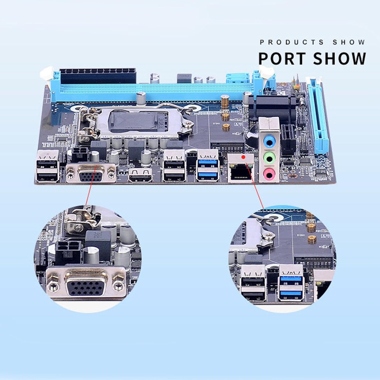
Figure 1.7: Close-up view of the rear I/O panel, showing the VGA, USB, LAN, and audio ports.

Figure 1.8: An example of a motherboard being installed into a computer case, illustrating the physical setup process.
2. Operating Instructions
Once all components are installed and connected, you can proceed with system operation.
2.1 Initial Boot-Up
- Power On: Ensure all power cables are securely connected. Press the power button on your computer case.
- BIOS/UEFI Access: During the initial boot sequence, press the designated key (usually DEL, F2, or F10) to enter the BIOS/UEFI setup utility. Refer to your system's on-screen prompts for the correct key.
2.2 BIOS/UEFI Configuration
The BIOS/UEFI allows you to configure system settings, boot order, and hardware parameters.
- Boot Order: Set the boot order to prioritize your operating system installation media (e.g., USB drive, DVD-ROM) or your primary storage drive.
- Date and Time: Adjust the system date and time if necessary.
- SATA Mode: Ensure the SATA mode is set correctly (e.g., AHCI for SSDs).
- Save and Exit: After making changes, save your settings and exit the BIOS/UEFI. The system will restart.
2.3 Operating System and Driver Installation
- Install OS: Follow the on-screen instructions to install your preferred operating system.
- Install Drivers: After OS installation, install the necessary drivers for the motherboard chipset, LAN, audio, and any other integrated components. These are typically provided on a driver CD or available for download from the manufacturer's website.
3. Maintenance
Regular maintenance helps ensure the longevity and optimal performance of your motherboard and system.
- Dust Removal: Periodically clean dust from the motherboard and components using compressed air. Ensure the system is powered off and unplugged before cleaning.
- BIOS Updates: Check the manufacturer's website for BIOS/UEFI updates. Updates can improve compatibility, stability, and performance. Follow the update instructions carefully to avoid system damage.
- Component Checks: Ensure all cables are securely connected and components are properly seated.
4. Troubleshooting
If you encounter issues, refer to these common troubleshooting steps.
- No Power/No Boot:
- Verify all power cables (24-pin ATX, CPU power) are securely connected.
- Check if the power supply unit (PSU) is functioning correctly.
- Ensure the front panel power switch is correctly connected to the motherboard.
- No Display:
- Ensure the monitor is connected to the correct video output (VGA or HDMI) on the motherboard or dedicated graphics card.
- Reseat the RAM modules. Try booting with one RAM module at a time.
- Check if the CPU is properly seated and the CPU cooler is installed correctly.
- Peripherals Not Detected:
- Try different USB ports.
- Ensure drivers for the motherboard chipset are installed.
- Check BIOS/UEFI settings for USB or SATA controller configurations.
- System Instability/Crashes:
- Check CPU and GPU temperatures.
- Run memory diagnostic tools to check RAM integrity.
- Ensure all drivers are up to date.
For further assistance, consult the manufacturer's support website or contact their technical support.
5. Specifications
Below are the technical specifications for the Tosuny Micro ATX H81 Motherboard.
| Feature | Specification |
|---|---|
| Brand | Tosuny |
| Model Number | Tosuny2pgvnhqkc7 |
| CPU Socket | LGA 1150 |
| Compatible Processors | Intel 4th Gen Core i3/i5/i7, Xeon E3 V3, Celeron G Series, Pentium G Series |
| Chipset | Intel H81 |
| RAM Technology | DDR3 SDRAM |
| RAM Slots | 2 x 240-pin DDR3 (Dual Channel) |
| Max RAM Capacity | 16 GB |
| RAM Clock Speed | 1066, 1333, 1600 MHz |
| Storage Interfaces | 1 x M.2 (NVMe/NGFF, with jumper for PCIE/SATA2.0/3.0), 2 x SATA 2.0 (3Gb/s), 1 x SATA 3.0 (6Gb/s) |
| Expansion Slots | 1 x PCI Express x16, 1 x PCI Express x1 |
| Rear I/O Ports | 4 x USB 2.0, 2 x USB 3.0, 1 x VGA, 1 x HDMI, 1 x RJ45 LAN, 1 x 3-in-1 Audio (Line In, Line Out, Mic) |
| LAN | 10/100/1000 Mbps Gigabit Ethernet |
| Audio | Realtek ALC662 6-channel HD Audio Codec |
| Main Power Connector | 24-pin ATX |
| CPU Power Connector | 4-pin ATX 12V |
| Form Factor | Micro ATX |
6. Warranty and Support
For information regarding warranty coverage, technical support, and driver downloads, please refer to the official Tosuny website or contact your retailer. Specific warranty terms may vary by region and retailer.
Manufacturer: Tosuny
Model: Tosuny2pgvnhqkc7
ASIN: B0CHMRL6S5