
ciciglow ciciglowg6uzo8f95m
ciciglow Micro ATX Motherboard (LGA 1155) User Manual
Model: ciciglowg6uzo8f95m
1. Introduction
This user manual provides comprehensive instructions for the installation, configuration, operation, and maintenance of your ciciglow Micro ATX Motherboard. Designed for LGA 1155 CPUs, this motherboard supports DDR3 memory, M.2 NVMe/NGFF storage, and offers versatile connectivity for various computing needs. Please read this manual thoroughly before proceeding with installation to ensure proper setup and optimal performance.
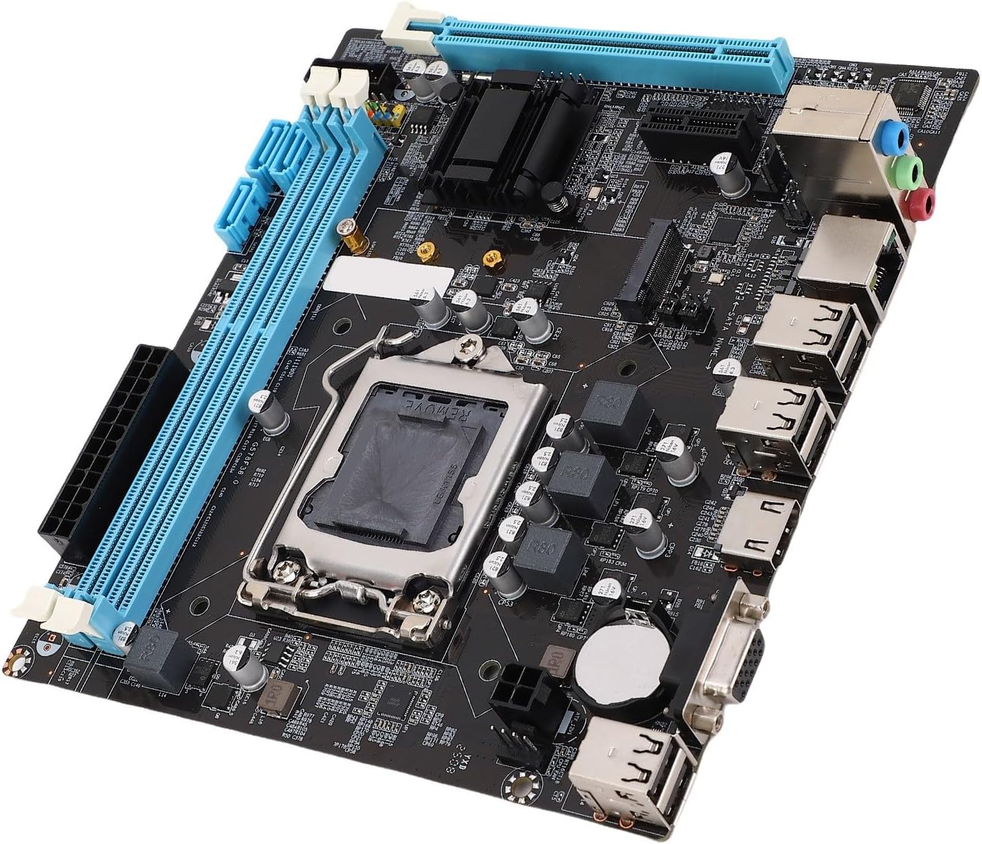
Figure 1: ciciglow Micro ATX Motherboard Overview
This image displays the ciciglow Micro ATX Motherboard from an angled perspective, showcasing its various components such as the CPU socket, RAM slots, PCIe slots, and I/O ports.
2. Setup and Installation
Follow these steps carefully to install your motherboard and its components. Ensure your system is powered off and unplugged before handling any internal components.
2.1 Motherboard Layout

Figure 2: Motherboard Component Layout
This diagram illustrates the key areas and connectors on the ciciglow Micro ATX Motherboard, including the CPU socket, memory slots, expansion slots, and various headers.
2.2 CPU Installation (LGA 1155)
- Locate the LGA 1155 CPU socket on the motherboard.
- Gently push down the load lever and pull it to the side to open the CPU socket retention frame.
- Align the triangular mark on your LGA 1155 CPU with the corresponding mark on the socket. Carefully place the CPU into the socket without forcing it.
- Close the retention frame and push the load lever back into its locked position.
- Apply thermal paste to the CPU and install the CPU cooler according to its manufacturer's instructions.
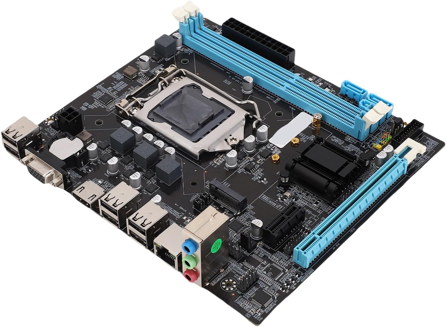
Figure 3: Close-up of LGA 1155 CPU Socket
This image provides a detailed view of the LGA 1155 CPU socket on the motherboard, showing the retention mechanism and pin array.
2.3 RAM Installation (DDR3)
- Open the clips at both ends of the DDR3 memory slots.
- Align the notch on the DDR3 memory module with the key in the memory slot.
- Press down firmly on both ends of the memory module until the clips snap into place.
2.4 M.2 NVMe/NGFF Installation
- Locate the M.2 slot on the motherboard.
- Insert the M.2 NVMe or NGFF SSD into the slot at a slight angle.
- Gently push down the SSD and secure it with the provided screw.
2.5 SATA Device Connection
Connect your SATA hard drives or SSDs to the SATA 2.0 ports on the motherboard using SATA data cables. Ensure power cables from your power supply are also connected to these devices.

Figure 4: Motherboard with Included Accessories
This image shows the ciciglow Micro ATX Motherboard alongside its included accessories: a SATA data cable and an I/O shield, essential for connecting storage devices and mounting the motherboard in a case.
2.6 Power Connections
- Connect the 24-pin ATX power connector from your power supply to the main power socket on the motherboard.
- Connect the 4-pin ATX 12V power connector to the CPU power socket, usually located near the CPU.
2.7 Front Panel Connections
Connect the front panel cables from your PC case (Power LED, HDD LED, Power Switch, Reset Switch, Front Audio, Front USB) to the corresponding headers on the motherboard. Refer to the motherboard layout diagram (Figure 2) for header locations.
2.8 Expansion Card Installation
Insert PCI Express X16 graphics cards or PCI Express X1 expansion cards into their respective slots. Ensure they are seated firmly and secured with a screw to the PC case.
3. Operating Instructions
3.1 Initial Boot-up
- After all components are installed and connected, ensure all power cables are securely plugged in.
- Press the power button on your PC case. The system should power on, and you should see a display on your monitor.
3.2 BIOS/UEFI Access
To access the BIOS/UEFI setup utility, press the DEL key repeatedly during the initial boot sequence. The BIOS allows you to configure system settings, boot order, and monitor hardware status.
3.3 Driver Installation
After installing your operating system, install the necessary drivers for the motherboard components (chipset, audio, LAN, etc.). These drivers are typically provided on a CD/DVD included with the motherboard or can be downloaded from the manufacturer's website.
3.4 Operating System Installation
Insert your operating system installation media (USB drive or DVD) and follow the on-screen prompts to install your preferred operating system. Ensure the boot order in BIOS is set to prioritize your installation media.
4. Maintenance
4.1 Cleaning Procedures
Regularly clean your computer's interior to prevent dust buildup, which can lead to overheating and component failure.
- Power off and unplug your computer before cleaning.
- Use compressed air to remove dust from fans, heatsinks, and other components.
- Wipe surfaces with a soft, lint-free cloth. Avoid using liquid cleaners directly on components.
4.2 BIOS Updates
BIOS updates can provide improved compatibility, stability, and new features. Check the manufacturer's website for the latest BIOS versions and follow their instructions carefully for updating. Incorrect BIOS updates can damage your motherboard.
4.3 CMOS Battery Replacement
The motherboard uses a CR2032 battery to retain BIOS settings and the system clock when the computer is powered off. If you experience issues with incorrect time or lost BIOS settings, the battery may need replacement.
- Power off and unplug the computer.
- Locate the CR2032 battery on the motherboard.
- Gently pry out the old battery and insert a new CR2032 battery with the positive (+) side facing up.
5. Troubleshooting
This section addresses common issues you might encounter.
5.1 No Power / No Boot
- Ensure all power cables (24-pin ATX, 4-pin ATX 12V) are securely connected to the motherboard and power supply.
- Verify that the power supply switch is in the "ON" position.
- Check front panel power switch connection to the motherboard.
- Test with a different power supply if possible.
5.2 No Display Output
- Ensure your monitor is connected to the correct video output (VGA or HD Multimedia Interface) on the motherboard or dedicated graphics card.
- Verify that the graphics card (if installed) is properly seated in its PCIe slot and has adequate power.
- Reseat RAM modules. Faulty or improperly seated RAM can prevent display output.
- If using a dedicated graphics card, ensure your CPU supports integrated graphics if you are trying to use the motherboard's video outputs.
5.3 USB Ports Not Functioning
- Check if the USB drivers are installed correctly in your operating system.
- Ensure front panel USB headers are correctly connected to the motherboard.
- Test with different USB devices and different ports to isolate the issue.
- A BIOS reset might resolve some connectivity issues.
5.4 System Instability / Crashes
- Check CPU and GPU temperatures. Overheating can cause instability.
- Run memory diagnostic tools to check for faulty RAM.
- Ensure all drivers are up to date.
- Verify power supply is sufficient for all components.
6. Specifications
Detailed technical specifications for the ciciglow Micro ATX Motherboard.

Figure 5: Key Motherboard Features
This image highlights the main features and specifications of the ciciglow Micro ATX Motherboard, including CPU socket type, memory support, and M.2 interface.
| Feature | Specification |
|---|---|
| Model | ciciglowg6uzo8f95m |
| CPU Slot Type | LGA 1155 (Supports I3/I5/I7/Pentium/Celeron Series CPU) |
| RAM Memory Technology | DDR3 (Dual Channel, Max 16GB, 1066/1333/1600MHz) |
| Storage Interface | M.2 NVMe/NGFF Slot, 3 x SATA 2.0 (3GB/s) Ports |
| LAN | 10/100Mbps LAN |
| Input/Output Interface | 6 x USB 2.0, 1 x VGA Port, 1 x HD Multimedia Interface Port, 1 x RJ45 Port, 1 x 3-in-1 Audio Port |
| Onboard Interface | 1 x 24Pin ATX Power, 1 x 4Pin ATX 12V Power, 2 x USB (supports 4 x USB 2.0), 1 x F Audio, 1 x F Panel, 1 x F Speaker, 1 x Fan, 1 x LPC Debug |
| Expansion Slots | 1 x PCI Express X16, 1 x PCI Express X1 |
| Integrated Audio | Onboard ALC 6 Channel HD Audio Codec |
| Structure | Micro ATX (17 x 19cm / 6.7 x 7.5in) |
| Battery | CR2032 (Inbuilt, 240mAh) |
| Chipset Type | Intel B250 (Note: Product description mentions H61, but specifications list B250. Following provided specifications.) |
| Platform | Linux (Compatible with various OS) |
7. Warranty and Support
7.1 Product Warranty
Please refer to the retailer's return policy for information regarding product returns and exchanges. For specific warranty details provided by ciciglow, please visit the official ciciglow website or contact their customer service.
7.2 Customer Support
For technical assistance, troubleshooting, or general inquiries about your ciciglow Micro ATX Motherboard, please contact ciciglow customer support.
- Manufacturer: ciciglow
- Online Support: Visit the ciciglow Store on Amazon for product information and potential support links.
Ask a question about this manual
Ask about setup, troubleshooting, compatibility, parts, safety, or missing instructions. Manuals+ will review the question and use this page’s manual context to help answer it.