1. Introduction
This manual provides comprehensive instructions for the installation, operation, and maintenance of the PerGar CLE6120UN+C Automatic Generator Start Controller. Designed for precise control and monitoring of generator sets, this module ensures reliable performance across various applications. Please read this manual thoroughly before installation and operation to ensure safe and efficient use of the product.
2. Safety Information
Always observe the following safety precautions to prevent injury or damage to the equipment:
- Electrical Hazard: Installation and maintenance should only be performed by qualified personnel. Ensure all power sources to the generator and controller are disconnected before performing any work.
- Proper Grounding: Ensure the controller and generator are properly grounded to prevent electrical shock.
- Environmental Conditions: Do not expose the controller to excessive moisture, dust, or extreme temperatures outside its specified operating range.
- Secure Connections: Verify all wiring connections are secure and correctly terminated to prevent malfunctions or damage.
- Read Instructions: Familiarize yourself with all instructions and warnings in this manual before operating the controller.
3. Product Overview
The PerGar CLE6120UN+C is an advanced automatic generator start controller designed for single generator set applications. It offers both manual and automatic start options, comprehensive monitoring, and protection functions for both electronic and non-electronic engines.
Key Features:
- High-precision performance with stable and consistent parameters.
- Supports both manual and automatic generator starting modes.
- Compact design for easy installation.
- Crucial engine monitoring and protection functions.
- Wide operating temperature range.
Controller Layout and Indicators:
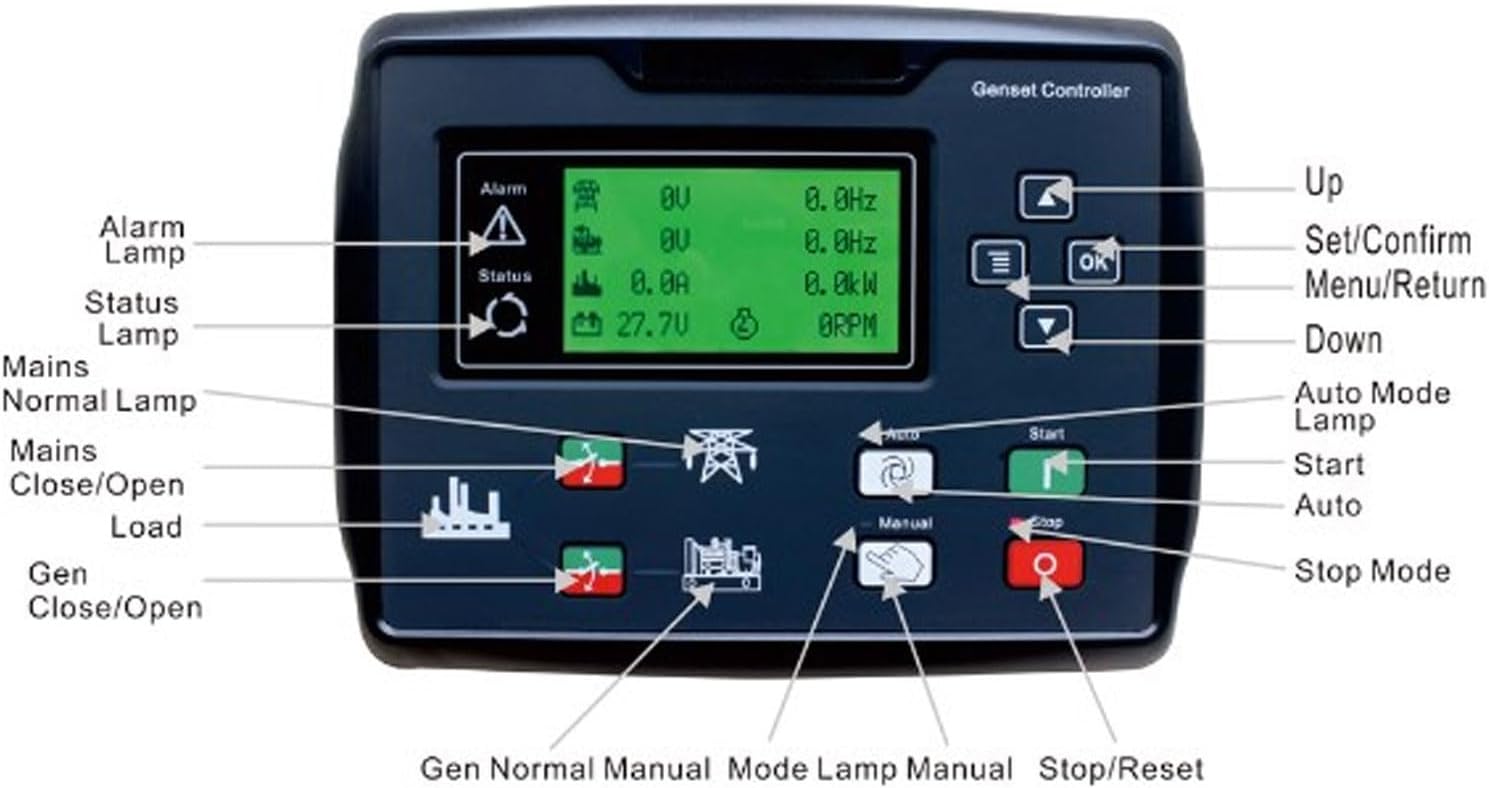
Figure 3.1: Front Panel Layout of the CLE6120UN+C Controller
The image above illustrates the front panel of the CLE6120UN+C controller, highlighting its various buttons, lamps, and the display screen. Key components include:
- Alarm Lamp: Indicates active alarms or fault conditions.
- Status Lamp: Shows the current operational status of the controller.
- Mains Normal Lamp: Illuminates when the main power supply is stable.
- Mains Close/Open Load: Buttons to control the main power load connection.
- Gen Close/Open: Buttons to control the generator output connection.
- Up/Down Buttons: Used for navigation within menus and adjusting parameters.
- Set/Confirm (OK) Button: Confirms selections and enters menu settings.
- Menu/Return Button: Accesses the main menu or returns to the previous screen.
- Auto Mode Lamp: Indicates when the controller is in automatic operation mode.
- Start Button: Initiates a manual generator start.
- Auto Button: Activates the automatic operating mode.
- Manual Button: Activates the manual operating mode.
- Stop/Reset Button: Stops the generator or resets active alarms.
- Gen Normal Manual Mode Lamp: Indicates generator normal operation in manual mode.

Figure 3.2: Front View of the CLE6120UN+C Controller
This image provides a clear view of the controller's front panel, showcasing its compact and functional design, ready for integration into a generator control system.
4. Setup
Proper installation is crucial for the reliable operation of the CLE6120UN+C controller. Refer to the wiring diagram provided with your generator set for specific connection points.
4.1 Mounting
- Select a suitable location for the controller, ensuring it is protected from direct weather exposure, excessive vibration, and extreme temperatures.
- Cut an appropriate opening in the control panel according to the controller's dimensions.
- Insert the controller into the opening and secure it using the provided mounting clamps.
4.2 Wiring
All wiring should comply with local electrical codes and standards. Use appropriate wire gauges for all connections.
- Power Supply: Connect the controller to a stable DC power source (15-360V, as specified). Ensure correct polarity.
- Generator Inputs: Connect the generator's voltage, current, and frequency sensing inputs to the corresponding terminals on the controller.
- Engine Control Outputs: Connect the controller's start, stop, fuel, and pre-heat outputs to the generator engine's control circuits.
- Mains Sensing: If using the automatic transfer switch (ATS) functionality, connect the mains voltage sensing inputs.
- Alarm Inputs/Outputs: Connect any external alarm sensors or indicators as required.
- Grounding: Ensure the controller chassis is properly grounded.
4.3 Initial Configuration
After wiring, power on the controller and navigate through the menu using the Up/Down and OK buttons to set initial parameters such as:
- Language settings.
- Generator type (e.g., 3-phase, 1-phase).
- Voltage and frequency nominal values.
- Engine parameters (e.g., crank time, cool-down time).
- Alarm thresholds.
5. Operating Instructions
5.1 Manual Operation
- Press the Manual button to enter manual mode. The Manual Mode Lamp will illuminate.
- Press the Start button to crank the generator engine. The controller will attempt to start the engine according to programmed crank cycles.
- Once the engine starts and stabilizes, the generator will be ready to accept load. Use the Gen Close/Open buttons to connect or disconnect the generator load.
- To stop the generator, press the Stop/Reset button. The engine will enter a cool-down period before shutting down.
5.2 Automatic Operation
In automatic mode, the controller monitors the mains power supply and automatically starts/stops the generator as needed.
- Press the Auto button to enter automatic mode. The Auto Mode Lamp will illuminate.
- The controller will continuously monitor the mains power supply.
- If the mains power fails or falls outside acceptable limits, the controller will initiate a generator start sequence after a programmed delay.
- Once the generator starts and stabilizes, the controller will transfer the load to the generator.
- When mains power is restored and stable, the controller will transfer the load back to the mains, allow the generator to cool down, and then shut it off.
- In automatic mode, pressing the Stop/Reset button will stop the generator and exit auto mode.
6. Maintenance
Regular maintenance ensures the longevity and reliable operation of your CLE6120UN+C controller.
- Cleaning: Periodically clean the controller's front panel with a soft, dry cloth. Do not use abrasive cleaners or solvents.
- Connection Checks: Annually, or as needed, inspect all wiring connections for tightness and signs of corrosion. Re-tighten any loose connections.
- Functional Test: Regularly perform a manual start and stop sequence to ensure all functions are operating correctly.
- Firmware Updates: Check the manufacturer's website for any available firmware updates, if applicable.
7. Troubleshooting
This section provides solutions to common issues you might encounter with the CLE6120UN+C controller.
| Problem | Possible Cause | Solution |
|---|---|---|
| Controller does not power on. | No power supply; incorrect wiring; blown fuse. | Check DC power supply connections and voltage. Verify wiring. Check and replace any blown fuses. |
| Generator fails to start in manual mode. | Low fuel; low battery; engine fault; incorrect wiring to starter. | Check fuel level and battery voltage. Inspect engine for faults. Verify starter motor wiring. |
| Generator starts but does not take load. | Load transfer switch fault; generator output fault. | Check the load transfer switch operation. Verify generator output voltage and frequency. |
| Controller displays an alarm. | Specific fault condition (e.g., over-voltage, under-frequency, low oil pressure). | Note the alarm code/message on the display. Refer to the controller's detailed alarm list (if available) for specific troubleshooting steps. Address the underlying fault. |
| Auto mode not engaging. | Mains power present; Auto button not pressed; configuration error. | Ensure mains power is genuinely absent or outside limits. Confirm Auto mode is selected. Check auto-start configuration parameters. |
8. Specifications
Technical specifications for the PerGar CLE6120UN+C Automatic Generator Start Controller:
| Feature | Detail |
|---|---|
| Manufacturer | PerGar |
| Model | CLE6120UN+C |
| Internal Model Reference | PerGarbopg4gx35i40696 |
| Input Voltage Range | 15-360V (as per product description) |
| Application | Single Generator Set Control (Manual & Automatic Start) |
| Engine Compatibility | Electronic and Non-Electronic Engines |
| ASIN | B0CHFKFXKW |
| Date First Available | April 30, 2024 |
| Spare Parts Availability | Information unavailable |
9. Warranty and Support
For warranty information and technical support, please refer to the documentation provided at the time of purchase or contact your vendor. PerGar products typically come with a standard manufacturer's warranty covering defects in materials and workmanship. Keep your proof of purchase for warranty claims.


